Chapter 2: interfacing to probe – AMETEK 7100 Leak Detect Stik User Manual
Page 10
8
Chapter 2: Interfacing to Probe
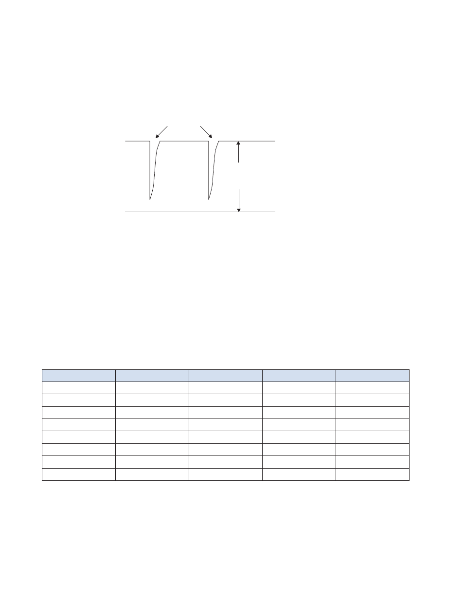
The pulse signals coming from the probe are superimposed onto the nominal 24 VDC power supply
connections. As shown in Figure 3, the pulses are negative-going and are large in amplitude, nominally 20
volts peak. The peak is negative going and only a few microseconds in duration. The leading edge is the
proper edge to use for timing purposes. The large signal amplitude offers high noise immunity.
Figure 3: Pulse Signals
A simple approach to getting 5 volt logic levels from the input signal is to simply set a comparator level as
shown in Figure 6. The comparator output can then be used to create a gate signal for a counter circuit. The
circuit example in Section 2.1 (page10) has a variation of this concept using a 5:1 pulse transformer to elimi-
nate the reference to 24 VDC and make the comparison relative to circuit common (with inverted polarity).
Probe power supply impedance will have an effect on pulse amplitude. Wire lengths will vary the pulse ampli-
tude. Wire has an associated inductance, resistance and capacitance which will change the amplitude of the
coupled pulse. Users may wish to load their circuit to minimize wire effects.
The chart below gives relative times by which a user can distinguish timing for various probe lengths.
Length
Float Position
Tstart
Tstop
D
t=Position
12"
1"
160msec
180msec
20msec
12"
12"
50msec
290msec
240msec
30"
1"
340msec
360msec
20msec
30"
30"
50msec
650msec
600msec
100"
1"
1040msec
1060msec
20msec
100"
100"
50msec
2050msec
2000msec
200"
1"
2040msec
2060msec
20msec
200"
200"
50msec
4050msec
4000msec
24 Volt Power
Supply Level
Pulse Pair
24 VDC
0 VDC