13 - byte ordering, 14 - modbus map, 15 modbus registers – AMETEK 7230 HT Digital Probe User Manual
Page 13
11
2.13 - Byte Ordering
In the Modbus slave confi guration, data can be ac-
cessed as integers (16 bits), long integers (32 bits),
and fl oating point value (32 bits). The order that the
bytes are sent must be known by the master in order to
assembly the bytes into the correct value. Byte order-
ing can have a few different terminologies.
1) Big/Little Endian.
2) Byte order by number, with 1 indicating the most
signifi cant part of the value, and 4 the least signifi -
cant.
3) Word/Byte, indicating which word (16 bits, high or
low) is sent fi rst, and which byte of the word (high or
low) come fi rst in that byte.
See the following example for accessing a product
reading of 46.60 inches. The integer value will be
4660, which translates to the hex number 0x00001234.
The individual bytes, 0x00, 0x00, 0x12, and 0x34 can
be sent the following 4 ways for 32 bits values:
1) Big Endian, Byte order 1234, High Word High Byte
(HWHB) Order sent: 0x00, 0x00, 0x12, 0x34
2) Little Endian, Byte order 4321, Low Word Low Byte
(LWLB) Order sent: 0x34, 0x12, 0x00, 0x00
3) Big Endian Byte Swapped, Byte order 2143, High
Word Low Byte (HWLB) Order sent: 0x00, 0x00,
0x34, 0x12
4) Little Endian Byte Swapped, Byte order 3412, Low
Word High Byte (LWHB)
Order sent: 0x12, 0x34, 0x00, 0x00
The individual bytes 0x12, and 0x34 can be sent the
following 2 ways for 16 bits values:
1) Big Endian, Byte order 12, High Byte fi rst (HB)
Order sent: 0x12, 0x34
2) Little Endian, Byte order 21, Low Byte fi rst (LB)
Order sent: 0x34, 0x12
2.14 - Modbus Map
Use the following tables to fi nd the register number
for the desired format. First, go to the section for the
number format you desire (integer, long integer, or
fl oating point). Then fi nd the table with the desired
units, English or metric. Then fi nd the value (product,
interface, average temperature, etc) in the left hand
column. Next, fi nd the desired byte ordering across the
top row. The corresponding entry at the intersection of
these 2 items gives the register that should be specifi ed
in the Modbus master request message. The number
of registers needed to obtain the value is also specifi ed
for each format.
NOTE:
HWHB = High Word High byte
LWHB = Low Word High Byte,
HWLB = High word low byte
LWLB = Low Word low byte
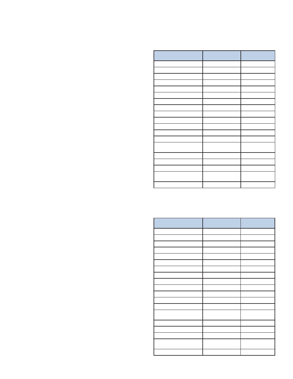
2.15 Modbus Registers
Integer (16 bit Signed) formats
Signed 16 bit Integer, 16 bits of data per register,
1 register needed to get value English Units,
inches and degrees F
Data
Big Endian,/
Hi Byte fi rst
Little Endian/
Low Byte fi rst
Product
31803
32003
Interface
31805
32005
product temperature
31807
32007
interface temperature
31809
32009
average temperature
31811
32011
status
31813
32013
Span 31815
32015
temperature 1
31817
32017
temperature 2
31819
32019
temperature 3
31821
32021
temperature 4
31823
32023
temperature 5
31825
32025
max temperature
31827
32027
temperature sensor 1 location
(closest to bottom)
31829
32029
temperature sensor 2 location
31831
32031
temperature sensor 3
31833
32033
temperature sensor 4 location
31835
32035
temperature sensor 5 location
(closest to top)
31837
32037
Software version
31899
32099
Data
Big Endian,/
Hi Byte fi rst
Little Endian/
Low Byte fi rst
Product
31903
32103
Interface
31905
32105
product temperature
31907
32107
interface temperature
31909
32109
average temperature
31911
32111
status
31913
32113
Span 31915
32115
temperature 1
31917
32117
temperature 2
31919
32119
temperature 3
31921
32121
temperature 4
31923
32123
temperature 5
31925
32125
max temperature
31927
32127
temperature sensor 1 location
(closest to bottom)
31929
32129
temperature sensor 2 location
31931
32131
temperature sensor 3
31933
32133
temperature sensor 4 location
31935
32135
temperature sensor 5 location
(closest to top)
31937
32137
Software version
31999
32199
Signed 16 bit Integer, 16 bits of data per register, 1
register needed to get value Metric Units,
centimeters and degrees C