AMETEK 955DQ Brik LDT User Manual
Page 9
9
1080 N. Crooks Road • Clawson, MI 48017 • 800.635.0289 • 248.435.0700 • Fax 248.435.8120 • www.AMETEKAPT.com
Once the LDT has been installed, wiring connections can
be made. There are two groups of connections you will
need to make. They are as follows:
• Power Supply Connections (including grounding
and shielding)
• LDT Input/Output Connections
Power Supply/Ground Connections
The 955DQ is available with two different connector
options, either Option H or Option E. Refer to the
part number labeled on your unit to determine which
connector you have. Always observe proper grounding
techniques such as single point grounding and isolating
high voltage (i.e. 120/240 VAC) from low voltage (10-30
VDC cables). Whenever possible, this cable should be
run in conduit by itself.
The power supply common, the cable shield and a
good earth ground should be connected together at the
location of the power supply common.
WARNING
!
Do not route the BRIK with Quadrature Output cable near
high voltage sources.
Option E: Uses a 12-Pin 12mm Euro Cordset with the
shield tied to the coupling nut. The 12-pin connector has
ten conductors of 24ga, with an aluminum/polyester/
aluminum foil with drain wire plus an overall braid of
tinned copper shield. Cable O.D. is .280. To reduce
electrical noise, the shield must be properly used.
Connect the cable’s shield to the controller system GND.
The connector shell on the probe is electrically connected
to the probe housing.
Option H: Uses a 10-Pin HRS connector. The 955DQ
BRIK with connector Option H uses a standard cable,
a multi-conductor Alpha 6334. It has ten conductors of
24ga, with an aluminum/polyester/aluminum foil with
drain wire plus an overall braid of tinned copper shield.
Cable O.D. is .270. To reduce electrical noise the shield
must be properly used. Connect the cable’s shield to
the controller system GND. The cable shield is not
connected at the transducer end.
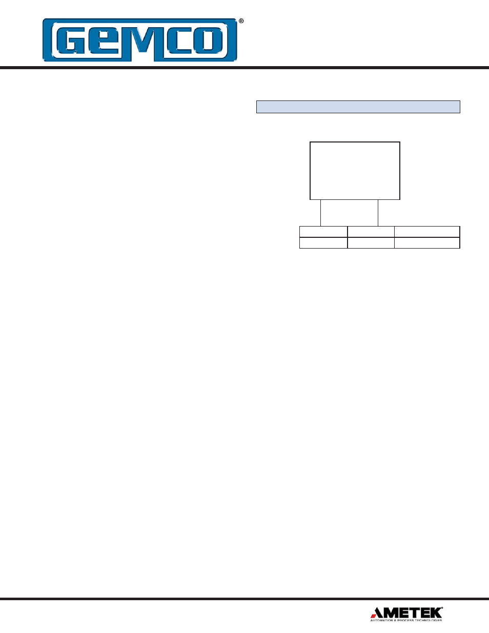
3.4 955DQ Wiring Connections
Figure 3.1 Power Supply Wiring
UNIPOLAR
Single ended
power supply
+13.5 to +30 VDC
+ COM
Pin 2 (red)
Pin 1 (black)
Connecter Option H
Pin 2 (brown)
Pin 7 (blue)
Connecter Option E