AMETEK 955DQ Brik LDT User Manual
Page 19
19
1080 N. Crooks Road • Clawson, MI 48017 • 800.635.0289 • 248.435.0700 • Fax 248.435.8120 • www.AMETEKAPT.com
Note: Contact our Technical Support at 1-800-635-0289
for custom configurations.
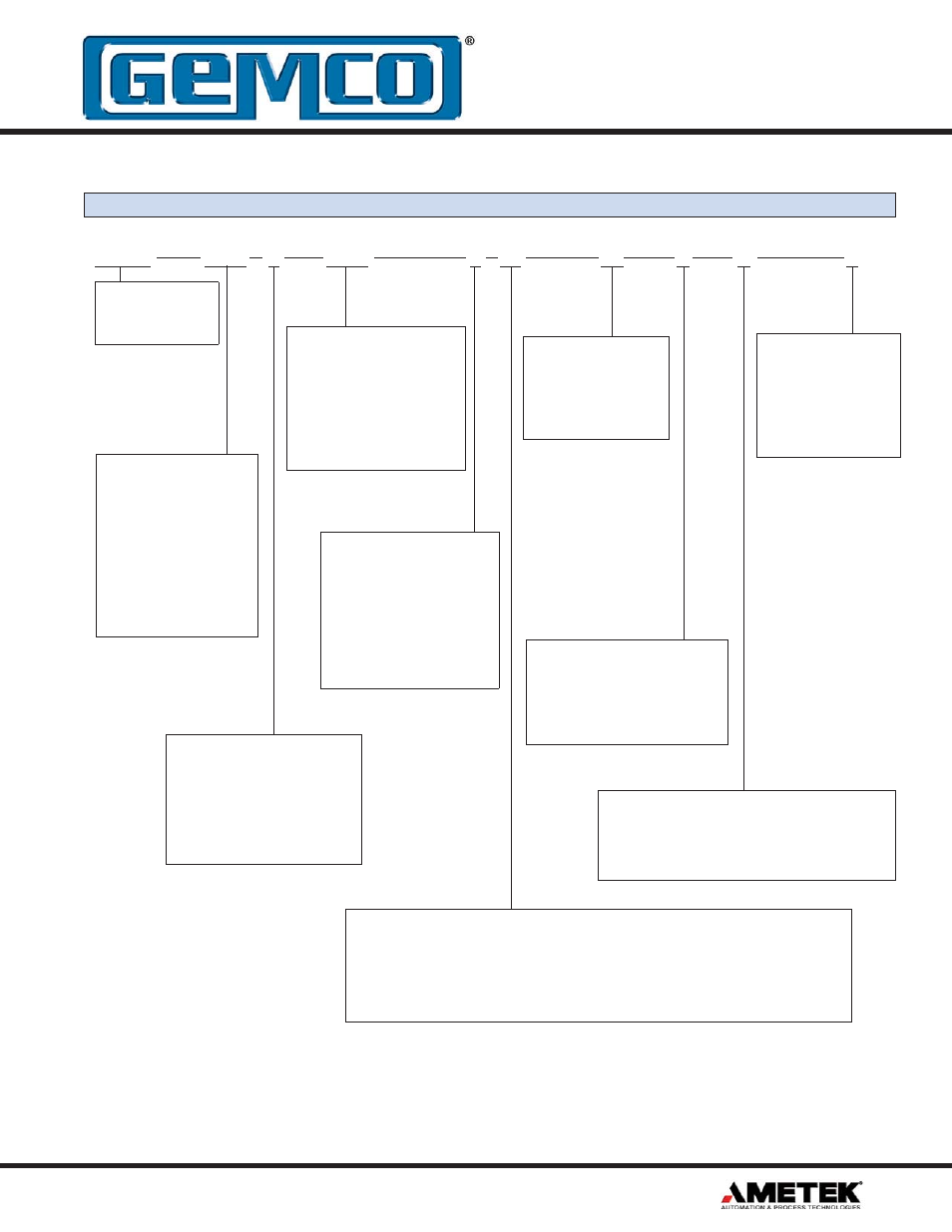
955DQ
0120
E
1000
E
F7
X1
N
D
X
Zero Offset Storage
V = Volatile (nonretentive)
N = Nonvolatile
(retentive, 100,000 storage cycles
maximum)
Output Drivers
D = Differential RS422 line driver, TTL compatible.
L = Differential line driver 13.5 to 30 VDC,
V out = V in (LDT Power) - 1 Volt.
Output Resolution
Cycles per inch, maximum
internal resolution is .001
inches. 1000 standard (Avail-
able range is 0001 through
9999). Consult factory for for
ranges above 9999.
Input Type
E = Sinking
(Typically used with sourcing
output type)
C = Sourcing
(Typically used with sinking
output type)
T = TTL Level
955DQ BRIK
Quadrature
Output
Stroke Length
Insert stroke length to 0.1
inch. Enter as a four-place
number.
Example A 12.0”
stroke enters as 0120. To
convert a metric stroke in
millimeters, multiply mil-
limeter value by 0.03937
to arrive at inch value.
Quadrature Cycle Output
Frequency Range
A1 = 1 KHz
A2 = 2 KHz
A3 = 5 KHz
F1 = 10 KHz
F2 = 25 KHz
F3 = 50 KHz
F4 = 75 KHz
F5 = 100 KHz
F6 = 150 KHz
F7 = 250 KHz
F8 = 500 KHz
F9 = 1.0 MHz
Output Mode
X1 = X1 Quadrature
D1 = Dual Magnet,
Difference between
magnets.
Options
X = None
E = Wet environment.
Electronics sealed to
IP68 Rating. Connector
Option E only.
Connector Style
H = HRS
Environmental Connector
E = Euro 12 Pin,
12mm Connector.
Consult factory for others.
Part Numbering
3.8 Catalog Numbering System