Chapter 3 programming & maintenance – AMETEK 955DQ Brik LDT User Manual
Page 7
7
1080 N. Crooks Road • Clawson, MI 48017 • 800.635.0289 • 248.435.0700 • Fax 248.435.8120 • www.AMETEKAPT.com
3.1 Quadrature Output
A new method of interfacing magnetostrictive transducers
offers customers an interface as common as analog
with the speed and accuracy of pulsed type signaling.
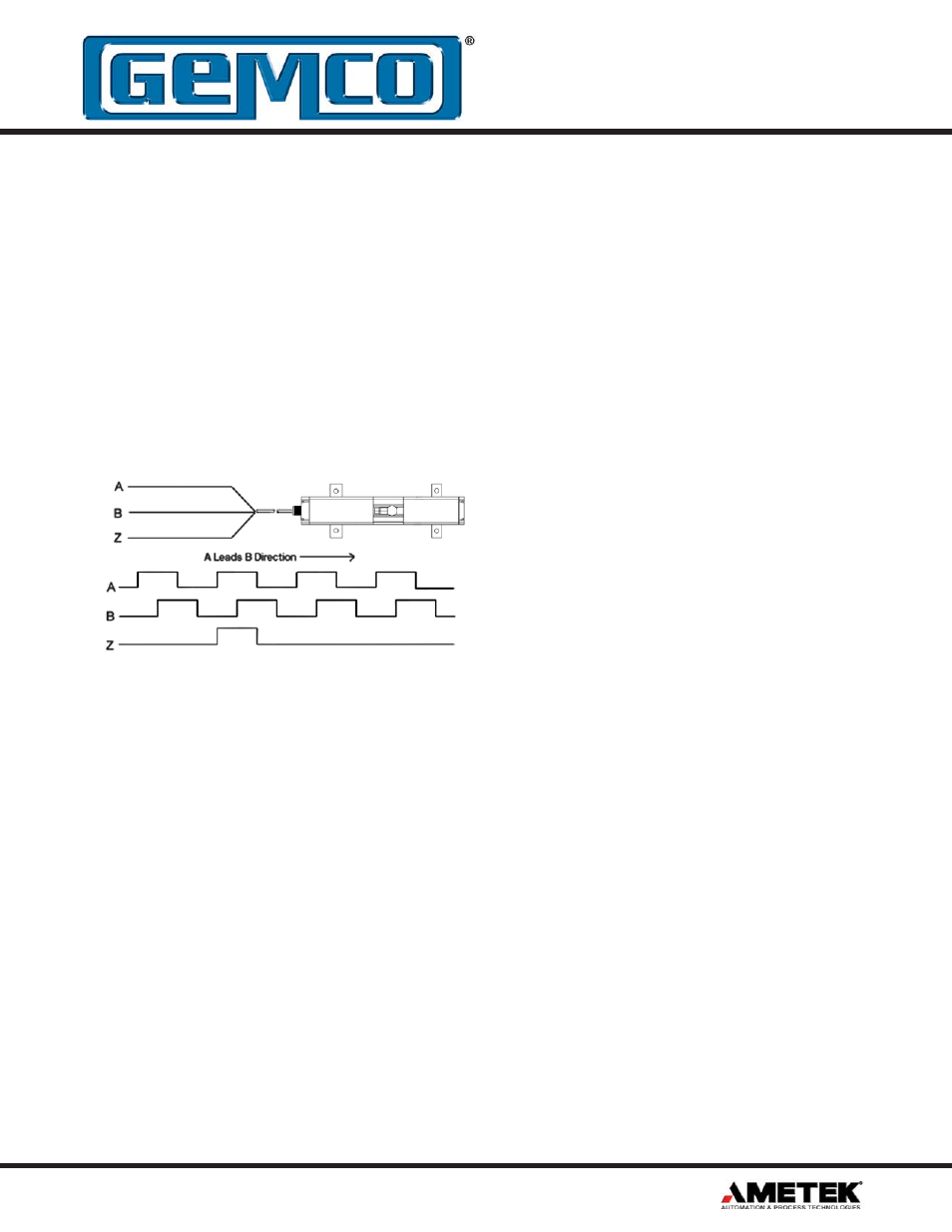
The GEMCO 955DQ LDT provides quadrature output
directly from the transducer to the controller (see drawing
below). The output from the transducer can be wired
directly to any incremental encoder input card, without
the need for a special converter module or PLC interface
card designed specifically for use with a pulsed output
magnetostrictive transducer.
The quadrature output provides absolute position data
in engineering units. This means that the need for the
calibration constant (wire speed) programming has been
removed, thereby eliminating the possibility of having an
improperly calibrated system. The output signal wires
are driven by differential line drivers, similar to the drivers
used in most magnetostrictive pulsed type transducers,
providing a high degree of noise immunity.
A unique feature of this transducer is a “burst” mode of
operation. An input on the transducer triggers a data
transfer of all the incremental position data relative to
the transducer’s absolute zero position. This can be
used to achieve absolute position updates when power
is restored to the system or anytime an update is needed
to re-zero or home the machine. Additionally, another
input to the transducer can be used to establish a “zero”
position for the transducer.
Chapter 3 Programming & Maintenance
3.2 Signal Connection Application Note
Overview
This application note will clarify the input and output
signals of the 955DQ quadrature probe.
Inputs
The quadrature probe has two inputs, the “zero” and
“burst” inputs. These inputs are “single ended”. That is,
the connection for each input consists of only one wire,
the corresponding signal wire. For these (single ended)
inputs, the signal is measured with reference to the
power supply ground, which is sometimes referred to as
“common”.
The quadrature probe is available with either +24 VDC
level signal thresholds or TTL level thresholds. The
signal voltage level required to activate the input for the
+24 VDC level signal is proportional to the power supply
voltage that the customer is supplying to the probe. This
level is approximately 41% of the power supply voltage.
For example, if the power supply voltage powering the
probe is exactly 24 VDC, the threshold voltage would be
approximately 9.84 volts.The TTL level threshold signals
are activated when these inputs exceed the typical TTL
level threshold, which is 2.0 VDC.
Additionally, for the 24 VDC level signals, the customer
can specify either a “sourcing” or “sinking” type of input.
A “sourcing” input type is pulled high internal to the probe.
To activate a “sourcing” input, the customer must pull the
signal lower than the threshold voltage to activate the
input. A “sourcing” input is usually driven by a “sinking”
output or a switch connected to ground. A “sinking”
input type is pulled low internal to the probe. To activate
a “sinking” input, the customer must pull the signal
higher than the threshold voltage to activate the input. A
“sinking” input is usually driven by a “sourcing” output or
a switch connected to the power supply.
It is important that the customer drive the signal levels
much greater or lower than the threshold voltages.
Asserting a signal with a voltage level close to the
threshold voltage could induce multiple activations of that
input (or none at all) and therefore produce unexpected
results or probe readings.