N0 usrin, Rogramming, Eter – Red Lion LDA User Manual
Page 6: 1 module 1 - s, 200v ran6e, 00 decpt, 00 ofset, Overview, Ignal, Nput
6
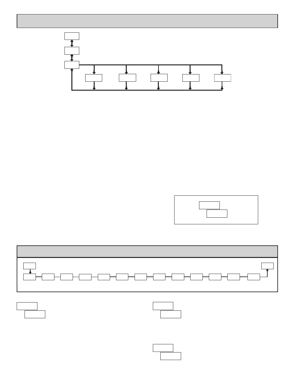
PROGRAMMING MODE ENTRY (PAR BUTTON)
It is recommended all programming changes be made off line, or before
installation. The meter normally operates in the Display Mode. No parameters
can be programmed in this mode. The Programming Mode is entered by
pressing the
PAR
button. If it is not accessible, then it is locked by either a
security code or a hardware lock.
MODULE ENTRY (SEL & PAR BUTTONS)
The Programming Menu is organized into five modules. These modules group
together parameters that are related in function. The display will alternate between
and the present module. The
SEL
button is used to select the desired
module. The displayed module is entered by pressing the
PAR
button.
MODULE MENU (PAR BUTTON)
Each module has a separate module menu (which is shown at the start of each
module discussion). The
PAR
button is pressed to advance to a particular
parameter to be changed, without changing the programming of preceding
parameters. After completing a module, the display will return to
.
Programming may continue by accessing additional modules.
SELECTION / VALUE ENTRY
For each parameter, the display alternates between the present parameter and
the selections/value for that parameter. The
SEL and RST
buttons are used to
move through the selections/values for that parameter. Pressing the
PAR
button,
stores and activates the displayed selection/value. This also advances the meter to
the next parameter.
For numeric values, the value is displayed with one digit flashing (initially
the right most digit). Pressing the
RST
button increments the digit by one or
the user can hold the
RST
button and the digit will automatically scroll. The
SEL
button will select the next digit to the left. Pressing the
PAR
button will
enter the value and move to the next parameter.
PROGRAMMING MODE EXIT (PAR BUTTON)
The Programming Mode is exited by pressing the
PAR
button with
Pro NO
displayed. This will commit any stored parameter changes to memory and
return the meter to the Display Mode. (If power loss occurs before returning to
the Display Mode, verify recent parameter changes.)
PROGRAMMING TIPS
It is recommended to start with Module 1 and proceed through each module in
sequence. When programming is complete, it is recommended to record the
parameter programming and lock out parameter programming with the user input
or programming security code.
FACTORY SETTINGS
Factory Settings may be completely restored in Module 2. This is useful
when encountering programming problems.
ALTERNATING SELECTION DISPLAY
In the explanation of the modules, the following dual display with arrows will
appear. This is used to illustrate the display alternating between the parameter
on top and the parameter’s Factory Setting on the bottom. In most cases,
selections and values for the parameter will be listed on the right.
Indicates Program Mode Alternating Display
Factory Settings are shown.
Parameter
Selection/Value
N0
USrIN
5.0 p
rograMMIng
the
M
eter
Parameters
Output
Setpoint
Parameters
Signal Input
Pro
DISPLAY
MODE
Panel Key
Function
Parameters
3-dSP
Parameters
Display and Front
NO
PAR
RST
PAR
PAR
PAR
PAR
2-SEC
1-INP
4-SPt
5-SEr
PAR
Serial
Setup
Parameters
Secondary
OVERVIEW
PROGRAMMING MENU
Display
Decimal
Point
Filter
Setting
Filter
Band
Input Value
for Scaling
Point 1
Display Value
For Scaling
Point 1
User Input
Assignment
Input
Range
PAR
rANGE
dECPt
FILtr
bANd
INP 1
dSP 1
INP 2
U-ASN
1-INP
Pro
User Input
Function
dSP 2
USrIN
Input Value
for Scaling
Point 2
Display Value
For Scaling
Point 2
StYLE
Scaling
Style
OFSEt
Display
Offset
Value
U-Act
User Input
Active Level
5.1 Module 1 - s
Ignal
I
nput
p
araMeters
(
1-INP
)
PARAMETER MENU
200v
rAN6E
INPUT RANGE
Select the input range that corresponds to the external signal. This selection
should be high enough to avoid input signal overload but low enough for the
desired input resolution. This selection and the position of the Input Range
Jumper must match.
200uA
200.00
µ
A
10u
2u
0.2u
0.002A
10.000 V
2.0000 V
200.00 mV
2.0000 mA
20.000 mA
200.00 V
20.000 V
200.00 mA
0.02A
200u
20u
0.2A
SELECTION
RANGE
RESOLUTION
RANGE
RESOLUTION
SELECTION
0.00
dECPt
0.000
0.0000
0.00
0.0
0
DISPLAY DECIMAL POINT
Select the decimal point location for the Input, MIN and MAX displays. This
selection also affects the
dSP1
and
dSP2
parameters and setpoint values and offset value.
0.00
OFSEt
DISPLAY OFFSET VALUE
The display can be corrected with an offset value. This can be used to
compensate for signal variations or sensor errors. This value is automatically
-19999
to
19999