Command response time, Receiving data from the meter – Red Lion LDA User Manual
Page 13
13
Command Response Time
The meter can only receive data or transmit data at any one time (half-duplex
operation). During RS232 transmissions, the meter ignores commands while
transmitting data, but instead uses RXD as a busy signal. When sending
commands and data to the meter, a delay must be imposed before sending
another command. This allows enough time for the meter to process the
command and prepare for the next command.
At the start of the time interval t
1
, the computer program prints or writes the
string to the com port, thus initiating a transmission. During t
1
, the command
characters are under transmission and at the end of this period, the command
terminating character (* or $) is received by the meter. The time duration of t
1
is dependent on the number of characters and baud rate of the channel.
t
1
= (10 times the # of characters) / baud rate
At the start of time interval t
2
, the meter starts the interpretation of the
command and when complete, performs the command function. This time
interval t
2
varies. If no response from the meter is expected, the meter is ready
to accept another command.
If the meter is to reply with data, the time interval t
2
is controlled by the use
of the command terminating character. The ‘*’ terminating character results in
a response time of 50 msec. minimum. This allows sufficient time for the
release of the sending driver on the RS485 bus. Terminating the command line
with ‘$’ results in a response time (t
2
) of 2 msec. minimum. The faster response
time of this terminating character requires that sending drivers release within 2
msec. after the terminating character is received.
At the beginning of time interval t
3
, the meter responds with the first
character of the reply. As with t
1
, the time duration of t
3
is dependent on the
number of characters and baud rate of the channel. At the end of t
3
, the meter is
ready to receive the next command.
t
3
= (10 times the # of characters) / baud rate
The maximum serial throughput of the meter is limited to the sum of the
times t
1
, t
2
and t
3
.
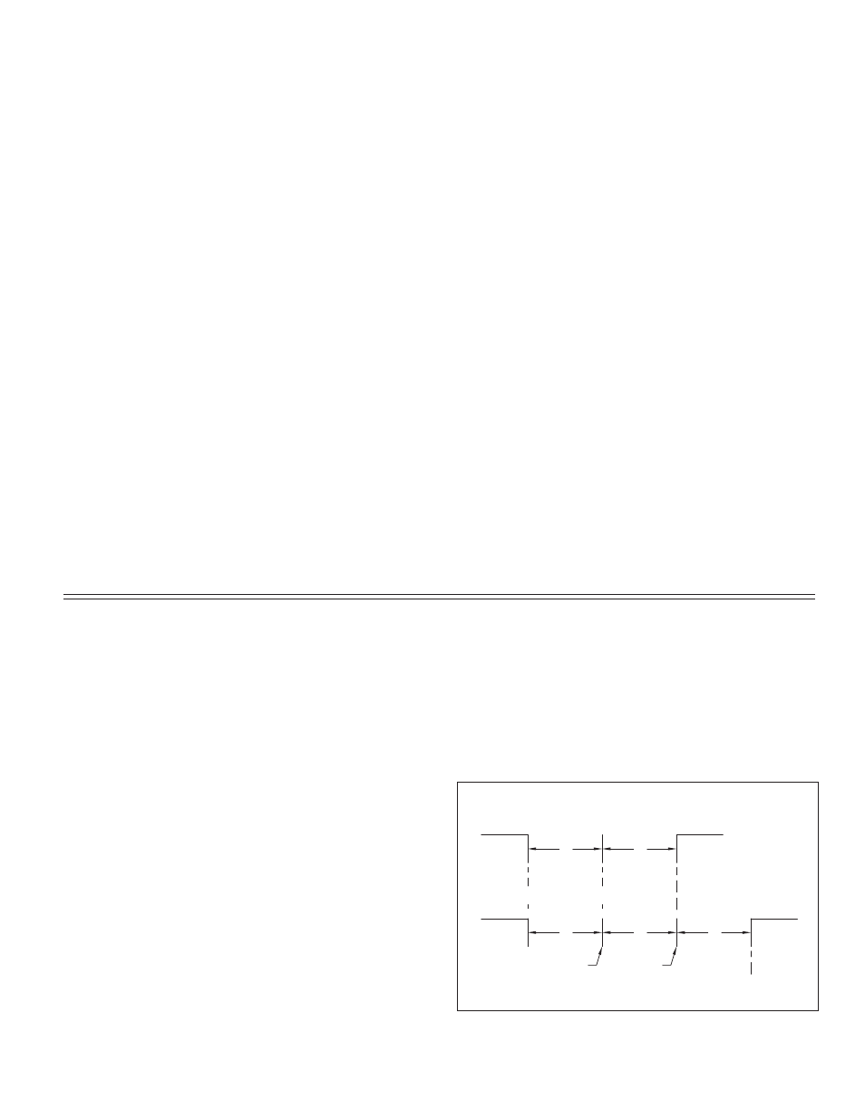
Ready
Ready
1
t
t
2
Ready
t
1
t
2
Ready
t
3
Command
String
Transmission
Meter
Response
Time
Command
Terminator
Received
First
Character
of Reply
Reply
Transmission
NO REPLY FROM METER
RESPONSE FROM METER
Time
Timing Diagram Figure
Receiving Data From The Meter
Data is transmitted from the meter in response to either a transmit command
(T), a block print request command (P) or a User Input print request. The
response from the meter is either a full field transmission or an abbreviated
transmission, depending on the selection chosen in Module 5.
Full Field Transmission
* These characters only appear in the last line of a block print.
The first two characters transmitted are the meter address. If the address
assigned is 0, two spaces are substituted. A space follows the meter address field.
The next three characters are the register mnemonic, as shown in the Register
Identification Chart.
The numeric data is transmitted next. The numeric field (bytes 7 to 15) is 9
characters long. This field consists of a minus sign (for negative values), a
floating decimal point (if applicable), and five positions for the requested value.
The data within bytes 9 to 15 is right-aligned with leading spaces for any
unfilled positions. When a requested value exceeds the meter’s display limits,
decimal points are transmitted instead of a numeric value.
The end of the response string is terminated with a
last line of a block print, an extra
separation between the print blocks.
Abbreviated Transmission
* These characters only appear in the last line of a block print.
The abbreviated response suppresses the node address and register ID,
leaving only the numeric part of the response.
Meter Response Examples:
1. Node address = 17, full field response, Input = 875
17 INP 875
2. Node address = 0, full field response, Setpoint 1 = -250.5
SP1 -250.5
3. Node address = 0, abbreviated response, Setpoint 2 = 250, last line of block
print 250
9 byte data field; 7 bytes for number, one byte for sign, one byte for
decimal point
20
19
18
17
16
7-15
3 byte Register Mnemonic field
4-6
3
2 byte Node Address field [00-99]
1, 2
Description
Byte
14
13
12
11
10
9 byte data field, 7 bytes for number, one byte for sign, one
byte for decimal point
1-9
Description
Byte