No abbr, No opt, 00 addr – Red Lion LDA User Manual
Page 12: Sending serial commands and data, Yes no
Sending Serial Commands and Data
When sending commands to the meter, a string containing at least one
command character must be constructed. A command string consists of a
command character, a value identifier, numerical data (if writing data to the
meter) followed by a command terminator character, * or $.
Command Chart
Command String Construction
The command string must be constructed in a specific sequence. The meter
does not respond with an error message to illegal commands. The following
procedure details construction of a command string:
1. The first 2 or 3 characters consist of the Node Address Specifier (N) followed
by a 1 or 2 character node address number. The node address number of the
meter is programmable. If the node address is 0, this command and the node
address itself may be omitted. This is the only command that may be used in
conjunction with other commands.
2. After the optional address specifier, the next character is the command
character.
3. The next character is the register ID. This identifies the register that the
command affects. The P command does not require a register ID character. It
prints all the active selections chosen in the Print Options menu parameter.
4. If constructing a value change command (writing data), the numeric data is
sent next.
5. All command strings must be terminated with the string termination
characters * or $. The meter does not begin processing the command string
until this character is received. See timing diagram figure
Register Identification Chart
Command String Examples:
1. Node address = 17, Write 350 to the Setpoint 1 value
String: N17VD350$
2. Node address = 5, Read Input, response time of 50 msec min
String: N5TA*
3. Node address = 31, Request a Block Print Output, response time of 2 msec min
String: N31P$
Transmitting Data to the Meter
Numeric data sent to the meter must be limited to transmit details listed in the
Register Identification Chart. Leading zeros are ignored. Negative numbers
must have a minus sign. The meter ignores any decimal point and conforms the
number to the scaled resolution. (For example: The meter’s scaled decimal point
position is set for 0.0 and 25 is written to a register. The value of the register is
now 2.5. In this case, write a value of 250 to equal 25.0).
Note: Since the meter does not issue a reply to value change commands, follow
with a transmit value command for readback verification.
12
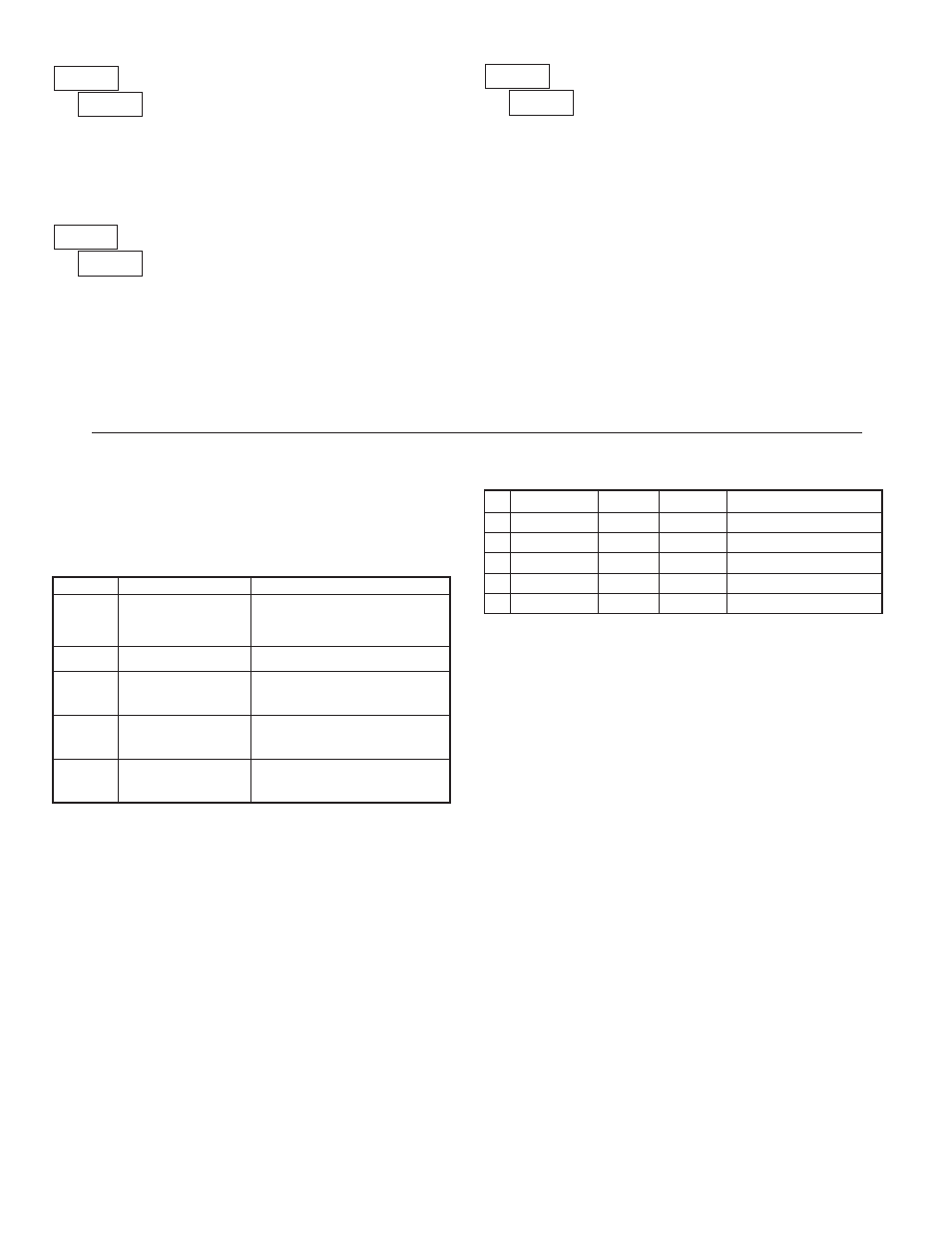
ABBREVIATED PRINTING
This parameter determines the formatting of data transmitted from the meter
in response to a Transmit Value command or a Block Print Request. Select
NO
for a full print transmission, consisting of the meter address, mnemonics, and
parameter data. Select
YES
for abbreviated print transmissions, consisting of the
parameter data only. This setting is applied to all the parameters selected in the
PRINT OPTIONS. (Note: If the meter address is 0, the address will not be sent
during a full transmission.)
NO
Abbr
YES
NO
PRINT OPTIONS
This parameter selects the meter values transmitted in response to a Print
Request. A print request is also referred to as a block print because more than
one parameter can be sent to a printer or computer as a block.
Selecting
YES
displays a sublist for choosing the meter parameters to appear
in the print block. All active parameters entered as
YES
in the sublist will be
transmitted during a block print. Parameters entered as
NO
will not be sent.
The “Print All” (
P ALL
) option selects all meter values for transmitting (
YES
),
without having to individually select each parameter in the sublist.
Note: Inactive parameters will not be sent regardless of the print option
setting. The Setpoint value will not be sent unless the setpoint is enabled
NO
OPt
YES
NO
DISPLAY
DESCRIPTION
FACTORY
SETTING
MNEMONIC
INP
Input
YES
INP
HI
Maximum
NO
MAX
LO
Minimum
NO
MIN
SPt-1
Setpoint 1
NO
SP1
SPt-2
Setpoint 2
NO
SP2
METER ADDRESS
Enter the serial node address. With a single unit, an address is not needed
and a value of zero can be used (RS232 applications). Otherwise, with multiple
bussed units, a unique address number must be assigned to each meter. The
node address applies specifically to RS485 applications.
00
Addr
0
to
99
Command Description
Notes
N
Node (meter)
Address Specifier
T
Transmit Value (read)
V
Value Change (write)
R
Reset
P
Block Print Request
(read)
Address a specific meter. Must be
followed by one or two digit node
address. Not required when node
address = 0.
Read a register from the meter. Must
be followed by a register ID character.
Write to register of the meter. Must be
followed by a register ID character and
numeric data.
Initiates a block print output. Registers
in the print block are selected in Print
Options.
ID Value Description MNEMONIC
Applicable
Commands Transmit Details (T and V)
A Input
INP
T, R
5 digit
B Maximum
MAX
T, R
5 digit
C Minimum
MIN
T, R
5 digit
D Setpoint 1
SP1
T, R, V
5 digit positive/4 digit negative
E Setpoint 2
SP2
T, R, V
5 digit positive/4 digit negative
Reset a min or max value or the
output. Must be followed by a register
ID character