Yes ren-n, No stb-n, 5 module 5 - s – Red Lion LDA User Manual
Page 11: 9600 baud, Bit data, Odd par, Ser baud data par addr abbr opt pro, Erial, Etup, Arameters
11
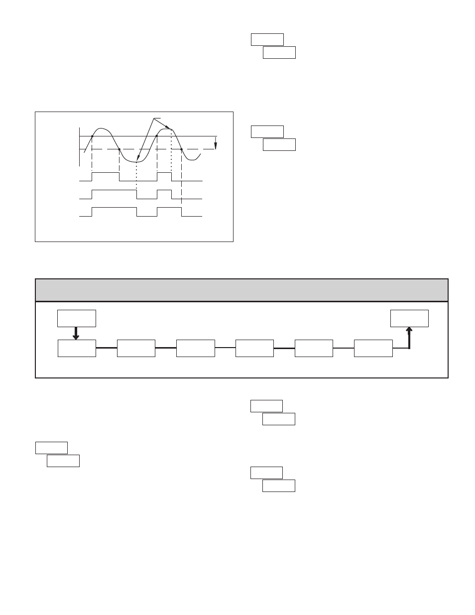
OUTPUT
STATE
OFF
ON
Hys
SP
Auto
OFF
ON
OFF
OFF
ON
OFF
ON
OFF
OFF
ON
OFF
ON
OFF
MANUAL
RESET
LAtCH
L-dLY
SP - Hys
( )
( )
( )
{
Setpoint Output Reset Actions
This parameter enables the
RST
button or user input to reset the output when
the display is reset.
Note: For this parameter to operate, the
RST
button or User Input being used
must be set to
dSP
and the Input value must be displayed. If these conditions are
not met, the output will not reset.
YES
rEn-n
OUTPUT RESET WITH DISPLAY RESET
YES
NO
When
YES
, the output is disabled (after a power up) until the trigger point is
crossed. Once the output is on, the output operates normally per the Setpoint
Action and Output Reset Action.
NO
Stb-n
STANDBY OPERATION
YES
NO
5.5 Module 5 - s
erIal
s
etup
p
araMeters
(
5-SEr
)
PAR
Data Bit
Baud Rate
Parity Bit
Options
Meter
Address
Abbreviated
Printing
5-SEr
bAUd
dAtA
PAr
Addr
Abbr
OPt
Pro
PARAMETER MENU
Module 5 is the programming module for the Serial Communications
Parameters. These parameters are used to match the serial settings of the LD
with those of the host computer or other serial device.
BAUD RATE
Set the baud rate to match that of other serial communications equipment.
Normally, the baud rate is set to the highest value that all of the serial
communications equipment is capable of transmitting and receiving.
9600
bAUd
9600
4800
38400
19200
2400
600
1200
300
corresponding “on” output is reset immediately and remains off until the
trigger point is crossed again. (Previously latched alarms will be off if power
up Display Value is lower than setpoint value.)
L-dLY
= Latch with delay reset action; This action latches the output on at the
trigger point per the Setpoint Action shown in Setpoint Output Figures. Latch
means that the output can only be turned off by the front panel
RST
button
or user input manual reset, serial reset command or meter power cycle. When
the user input or
RST
button is activated (momentary action), the meter
delays the event until the corresponding “on” output crosses the trigger off
point. (Previously latched outputs are off if power up Display Value is lower
than setpoint value. During a power cycle, the meter erases a previous
L-dLY
reset if it is not activated at power up.)
DATA BIT
Select either 7- or 8-bit data word length. Set the word length to match the
other serial communications equipment on the serial link.
7-bit
dAtA
8-bit
7-bit
PARITY BIT
This parameter only appears when the Data Bit parameter is set to a 7-bit
data word length. Set the parity bit to match that of the other serial equipment
on the serial link. The meter ignores parity when receiving data and sets the
parity bit for outgoing data. If parity is set to
NO
, an additional stop bit is used
to force the frame size to 10 bits.
Odd
PAr
EVEN
Odd
NO