HighPoint RocketRAID 2314 User Manual
Page 15
RocketRAID 231x Hardware Description/Installation
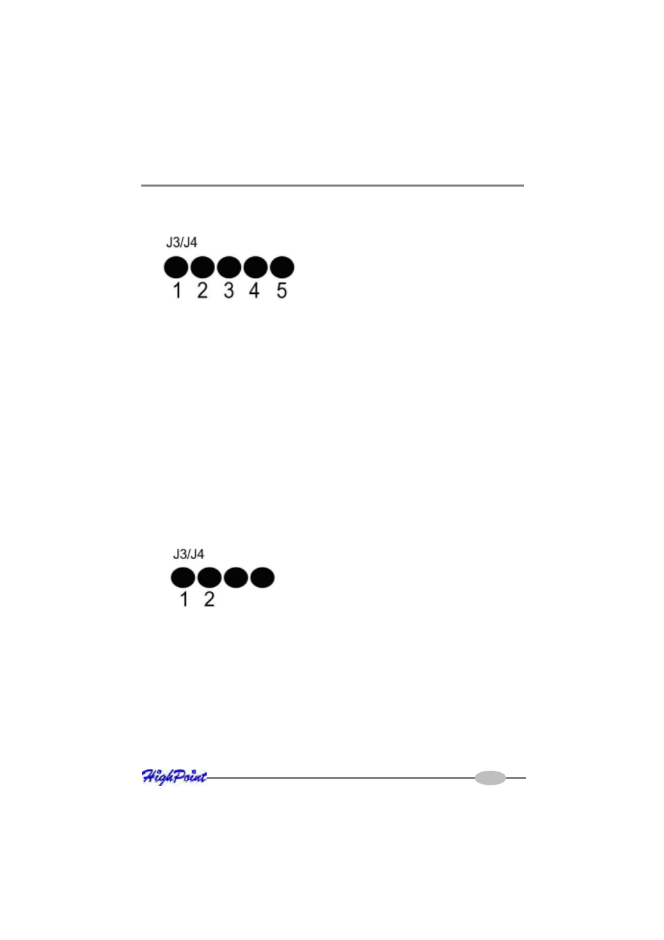
The following diagram describes the connector pin definitions for both of these LED
connectors. J3 provides LED support for Disk Failure, while J4 supports Disk Activity.
Pins 1-4 represent each SATAII channel/port (Pin 1 = Port 1, Pin2 = Port 2, etc.).
Pin 5 is for power (VCC, 3.3v)
Note:
these LED connectors were designed for use with SATA and SATAII
backplanes (typically used in hot-swap enclosures or drive bays designed for use
with server chassis). They were not designed for use with standard 2-pin LED’s
(commonly used by desktop chassis).
LED Connections – RR2312
The RocketRAID 2312 provides LED connectors for it’s two internal SATA channels.
Pins 1 and 2 represent SATA channel 1 and 2 respectively. Pins 3 and 4 are not
utilized.
J3 provides LED support for Disk Failure, while J4 supports Disk Activity.
Note:
As with the RR2310 model, these LED connectors were designed for use with
SATA and SATAII backplanes (typically used in hot-swap enclosures or drive bays
designed for use with server chassis). They were not designed for use with standard
2-pin LED’s (commonly used by desktop chassis).
LED Connections – RR2314
The RocketRAID 2314 does not provide LED connectors. It was designed for use
with external drive enclosures, rather than internal disk configurations.
2-4