Flaming River Keyless Ignition Systems User Manual
Page 8
8
9
Installation Instruction For Remote Keyless Entry (RKE) System
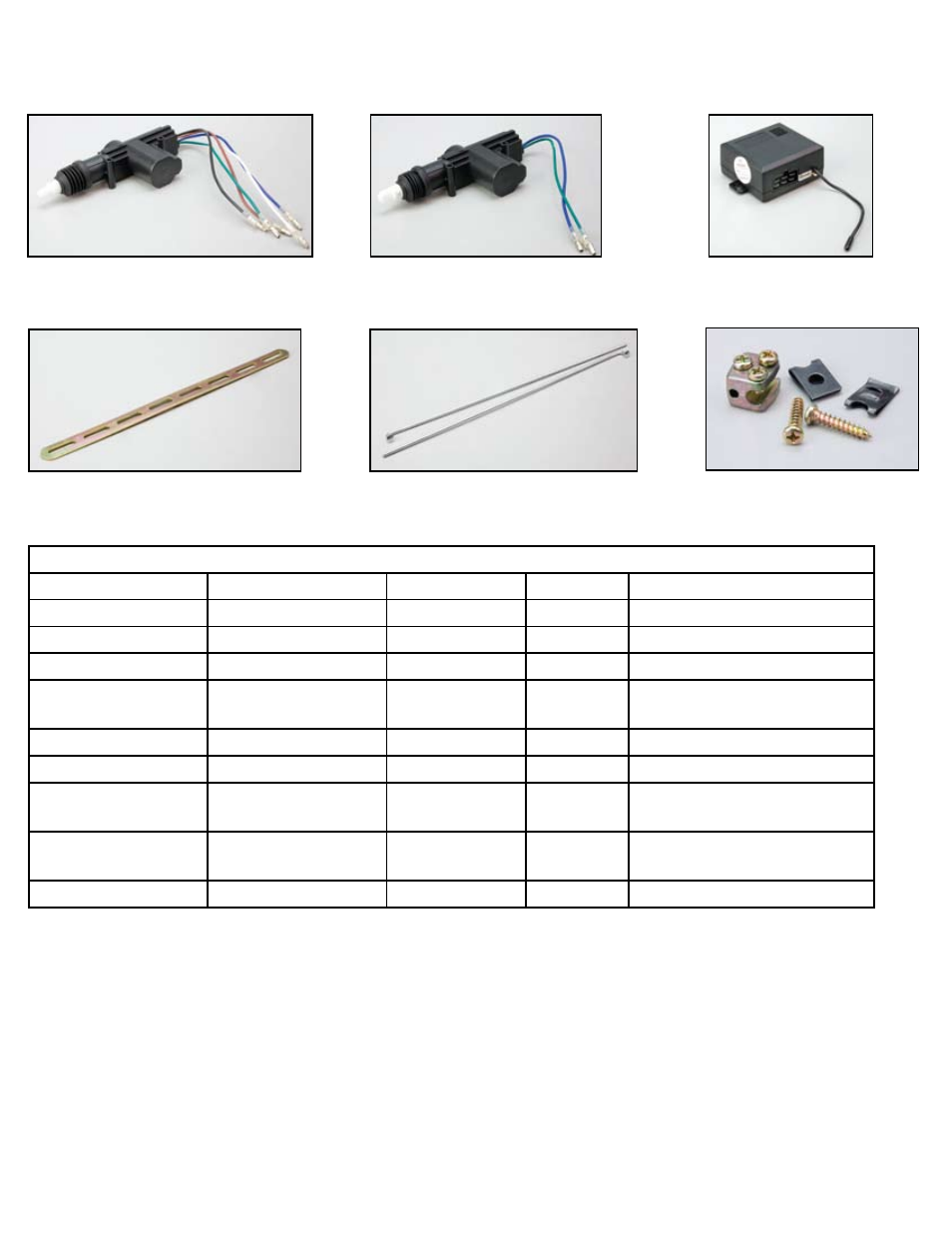
A. COMPONENTS & PARTS ILLUSTRATIONS:
Components & Parts Specification List
Model No.
Name
Specifications
Quantity
Usage
ML
Main Control Lock
5 pins
1
For driver's Side Front Door
SL
Sub-Control Lock
2 pins
3
For Other Three Doors
CL
Central Control Box
-
1
-
SB
Support Board
-
4
For Fixing Main Control Lock And
Sub-Control Lock
CR
Control Rod
-
4
-
BR
Rod Fixing Block
-
4
-
Ssl
Sub-Control Lock
Fixing Screws
TS MS*8
8
-
Bns
Support Board
Bolt-Nut Sets
M5*8
8
-
Control Wires
UL Qualified
1
-
B. INSTALLATION PROCEDURES:
1. Installation of all control locks:
a. Unfasten the internal decoration board of the doors.
b. Be sure to position the control lock to the correct direction shown in fig. 1 (make sure the main shaft in the control lock is moving in parallel to the moving direction of the door-
lock knob snap-slot).
2 a. Either choose to apply the support board (SB) for installing the main control lock (ML) and the Sub-Control Lock (SL)
b. Or to drill two holes, with dia. 5-6mm, in the internal side of the car doors, then fasten the control locks with TS M5*14 screws (Ssl) directly
3. Assemble the control rod (CR) to the control lock (adjust to make both end-sections of the rod parallel to each other as shown in fig. 2).
4. Assemble the control rod (CR) and door-lock knob rod into the rod fixing block (BR) (as shown in fig. 3), be sure to adjust until adequate motion stroke is found, then fasten the rods
with the Hexahole cap bolts tightly (adjustment of stroke is shown in fig. 4).
Main Control Lock
(ML)
Sub-Control Lock
(SL)
Central Control Box
(CL)
Support Board
(SB)
Control Rod
(CR)
Rod Fixing Block
(BR)