Step 6, Step 7 – Flaming River Keyless Ignition Systems User Manual
Page 4
4
5
STEP 6
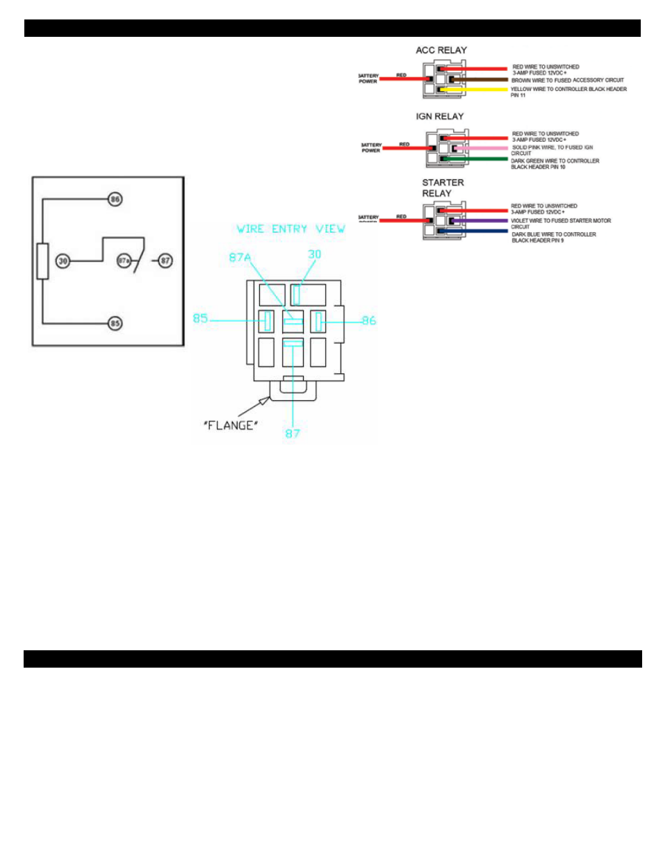
Relay pack wiring (please refer to the relay pack wiring diagram).
1. Operation: The system uses standard automotive rated Form C relays to
switch the high current loads. A schematic of the relay is shown along with the
pinouts as viewed from the wire entry side. The relay part number, pinouts, and
load ratings (40 amps for the N.O. pin) are printed on the sides of the relays. The
relays do not use internal diode or resistor snubbers.
FOR ALL RELAYS: Pins 30 and 86 are connected to B+, 12VDC. Pin 85 is pulled
low by the system to power the coil; pin 87 is the high current output which is
enabled when the coil is powered. Pin 87A is not used.
Form C Relay
Relay Pinouts
2. Prior to any connection to the main harness, the individual relay circuits may be tested by momentarily switching the yellow, green, or blue wires to ground, this will activate the
relay coils , and enable the relay load circuits on pin 87 of the relays.
The yellow, green, or blue wires (from relay coil pin 85) are then connected to the same color and marking of wires from the main harness. Wire lengths may be shortened or
lengthened as needed.
3. IMPORTANT: A test lamp or other method should be used to verify proper operation and sequencing of the relays with the system prior to hard-wiring the relays to the ACC, IGN, and
STARTER circuits. It is important to run this test to ensure that any neutral transmission safety interlocks and clutch interlocks are completely functional, and that the relays will
function correctly when the yellow, green, or blue wires are switched to ground.
4. All of the red wires (to 12VDC) from the relay pack may be spliced together to a larger gage single battery wire. This circuit should contain a fuse or circuit breaker with adequate
capacity to handle the combined ACC / IGN / STR loads.
Alternatively, the 3 red relay coil wires (these are the smaller 18 gauge wires at pin 86 of the relay packs) may be connected to the dedicated low power circuit, with the combined
ACC / IGN / STR red wires connected to a high current fused or circuit breaker protected circuit.
STEP 7
1. Wire the main harness.
a. The red wire from the main harness should be terminated to the dedicated 3 amp constant hot fused circuit.
b. The black wire should be terminated to an adequate ground point.
c. The blue, green and yellow wires are connected to the mating wires on the relay harness. These wires are switched by the control unit to ground in order to switch the
corresponding relays. The wires should never be tied directly to 12 volts without a load, as this will short the output transistors and damage the unit.
d. The docking station cable should be routed and connected at this time.