Après a v ant, Troubleshooting – Actron CP7954 User Manual
Page 3
3
5.
Choose a wire size from the table in Dia-
gram
3 that is a large enough gauge (larger
size wire has a smaller gauge number) to
handle the maximum rated output of your
vehicle’
s alternator/generator
. Obtain two
lengths of this size wire that are each long
enough to go from the location that was cho-
sen in Step 3, to the ammeter
’s
mounting
location at the dashboard. Attach closed-eyed
type connectors (Diagram 4), to each end of
both wires.
6
.
At the location you chose in Step 3, discon-
nect all the wires at the connection except
the wire going to the battery
.
7
.
Connect an end of one of the wires you ob-
tained in Step 5 to all the wires you discon-
nected in Step 6.
8
.
Connect an end of the remaining wire from
Step 5 to the connection in Step 6 that still
has the battery wire attached to it.
9
.
If your system matches Drawings 2, 3, or 6,
connect the wire you disconnected in Step 4
to the wires already connected in Step 7. Use
an additional piece of similar sized wire to join
these wires, if necessary
.
10.
Insulate all connections and use a suitable
method to fasten down the wires in Steps 7
and 9.
11
.
Route the two ammeter wires to the mount-
ing location for the ammeter
. Insulate the
opening in the firewall they pass through.
12.
Mount the gauge and attach the remaining
end of the wire from Step 7 to the ammeter
connection post marked with a “+”. Follow
the sequence of washer-wire-nut shown in
Diagram 4.
1
3
.Attach the remaining end of the wire from
Step
8 to the ammeter connection post
marked with a “–” sign, again following Dia-
gram 4.
14.
Reconnect the battery ground cable. As you
do, watch for sparks and check if the wiring
you worked with is getting warm. If either con-
dition is noted, IMMEDIA
TEL
Y disconnect the
battery ground cable and read the
T
rou-
bleshooting
section.
TROUBLESHOOTING
1
.
If, when you reconnected the battery ground
cable, you noticed sparks or any of the wiring
getting warm, check that all connections are
properly located, and insulated from ground-
ing.
2
.
With the vehicle not running and the battery
reconnected, turn on the headlights’ high
beam and observe the ammeter
. The gauge
should show a drain (–) condition. If a charge
(+) condition is shown, reverse the wires on
the “+” and “–” posts on the back of the am-
meter
. If the ammeter shows no change, the
circuit from Ignition/Accessory (I) has not been
properly included in the connections to the
“+” side of the gauge.
MAX. AMP
.
WIRE SIZE
RA
TING
12
25
10
40
86
5
69
5
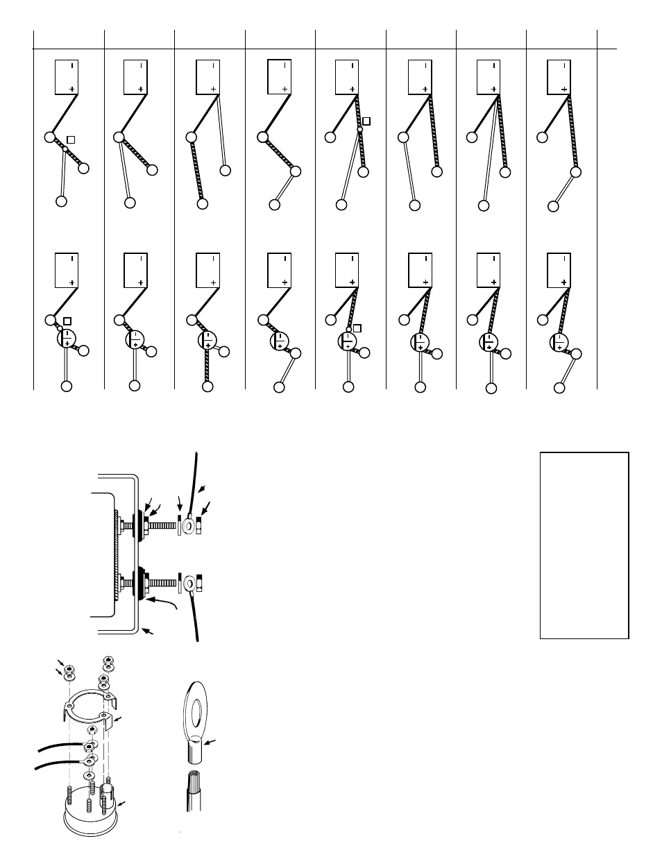
Diagram 3
CLOSED-EYE CONNECT
O
R
MAKE SURE CRIMP IS GOOD
2” AMMETER ONL
Y
:
3 PRONG U-BRACKET
AMMETER
NUT
WASHER
GROMMET
U-BRACKET
WIRE
F
L
A
T
W
ASHER
NUT
W
ASHER
AMMETER
DO NOT LEA
VE ANY HARDW
ARE
OUT OF THESE CONNECTIONS
Diagram 4
NUT
10
A
I
B
S
B
S
I
A
I
A
B
S
A
B
S
I
A
B
S
I
B
S
A
I
A
I
B
S
Z
A
B
S
I
Z
B
S
I
A
I
B
S
A
B
S
B
S
B
S
I
A
I
A
B
S
B
S
I
A
I
B
S
A
B
S
A
I
Z
B
S
Z
I
A
1
2
3
4
5
6
7
8
APRÈS
A
V
ANT
Schéma 2