Troubleshooting – Actron CP7009 User Manual
Page 2
2
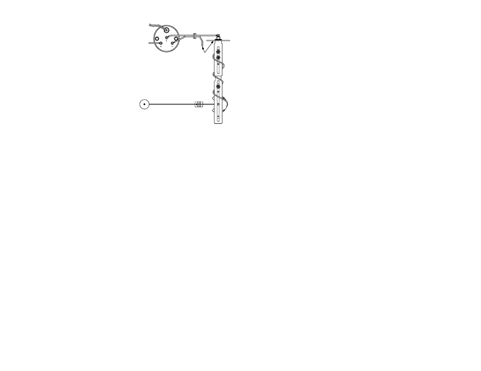
GROMMET
to Fuse
BOX
Figure 3
GROUND WIRE
and sender
to ground on
Fuel tank
Gauge to Sender Connection
5. read the fuel level tank sender instructions and
install the sender.
6. Refer to Figure 3. Route a length of 18-gauge
insulated copper wire from the gauge to the
sender. connect the wire to the sender. connect
the other end of the wire to the connection post
on the back of the gauge marked “S”.
7. Make sure the fuel level sender is grounded to
ground on fuel tank or to the same point as fac-
tory sender.
8. Connect a second length of 18-gauge insulated
copper wire to the connection post on the back
of the gauge marked “-“. Connect the other end
of the wire to the point where the fuel level tank
sender is grounded.
9. Connect a third length of 18-gauge insulated cop-
per wire to the connection post on the back of the
gauge marked “+”. Connect the other end of the
wire to the fuse box where the wire will receive
+12 volts of power whenever the ignition key is
in a start, on or accessorY position.
10. complete the mounting of the gauge.
11. reconnect the battery ground cable.
12. be sure that all water has been removed and
the tank thoroughly dried before refilling.
13. Refill the fuel tank, observing the gauge for
proper operation as you do.
TROUBLESHOOTING
If the gauge indicates too low a fuel level compared to
the actual level, re-check all connections, particularly
the ground connections, as this will cause increased
electrical resistance and false low readings.If the
gauge does not indicate full or empty at the proper
fuel levels, re-check the sender to make sure that
the float arm moves freely between the two stop
tabs on the sender.