Troubleshooting – Actron CP7005 User Manual
Page 2
2
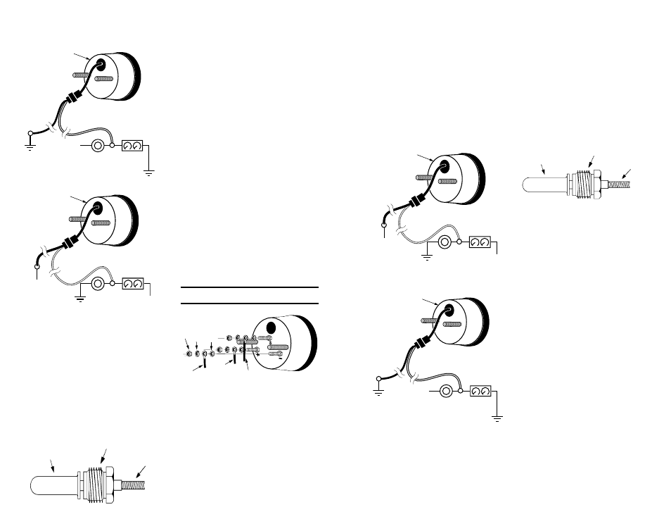
4. connect the blue and white wires using either
Figure 2a or Figure 2b.
7
cAPILLARY
Tube
Figure 3
cAPILLARY Tube TIP
cAPTIVe FITTINg
For Mechanical Gauges:
1. Drain the fluid level in the system to below the
sender’s mounting location which is normally the
factory’s warning light sender location.
2. Route the capillary tubing through the mounting
hole for the gauge and then through the firewall,
protecting the tubing from rough edges. Form at
least one 3” or larger loop of tubing as it comes
through the firewall and route the remainder to
the sender mounting locations.
3. Remove the warning light sender and install the
proper adapter fitting into the engine block.
4. Insert the capillary tube tip into the adapter’s hole
and then tighten, with moderate pressure only,
the captive fitting (Figure 3) into the adapter. Do
not overtighten. sealing tape or compound may
be used on either connection.
Figure 2a
For Positive Dimmer Controls
gAuge
bLue
WhITe
DAsh
LIghTINg
To
gRouND
DImmeR
coNTRoL
To
gRouND
+12V
Figure 2b
For Negative Dimmer Controls
To
gRouND
DImmeR
coNTRoL
DAsh
LIghTINg
WhITe
bLue
+12V
+12V
gAuge
NOTE: Do NOT leave any hardware out of these
connections.
Figure 4
Wire Connections
N
u
T
Lo
ck
W
A
she
R
FLA
T
W
As
h
eR
gRouND
WIRe
+12V
WIRe
seNDeR
ouPuT
gAuge
5. complete the mounting of the gauge.
6. Refill the fluid level to its normal level.
7. start the engine and observe the fitting
connections for leaks and the gauge for proper
operation.
For Electrical Gauges:
1. Drain the fluid level in the system to below the
sender’s mounting location, which is normally
the factory’s warning light sender location.
2. Remove the warning light sender and insulate
the end of the sender wire. Install the proper
adapter fitting into the engine block, if needed. If
an adapter is needed, use either the NPT-thread
adapter or metric-thread adapter (included).
3. Install the gauge’s sender into the warning
light sender’s mounting location in the engine
block.
4. Run a length of 18-gauge insulated copper
wire from the gauge’s mounting location to the
sender’s mounting location.
5. Attach the 18-gauge wire onto the top of the
gauge’s sender.
6. After you have mounted the gauge, connect the
sender wire to the ”s” connection post as shown
in Figure 4. Do not over tighten.
7. connect one end of another length of 18-gauge
insulated copper wire to “–” connection post as
shown in Figure 4, and the other end of the wire
to a good ground source.
8. connect a third length of 18-gauge insulated
copper wire to the “+” connection post as shown
in Figure 4, and the other end of the wire should
be connected to the fuse box where the wire
will receive +12 volts of power whenever the
ignition key is in the sTART, oN or AccessoRY
position.
9. complete the mounting of the gauge.
10. Refill the fluid level to its normal level.
12. start the engine and observe the fitting/sender
connections for leaks and the gauge for proper
operation.
TROUBLESHOOTING
If your electrical gauge reads lower than you would
expect, check all electrical connections, particularly
grounding connections. Any poor connection will
increase electrical resistance resulting in a false
low reading.
1. Il est recommandé de débrancher le câble de
masse de la batterie avant toute intervention
électrique.
2. elija para el montaje del indicador un lugar tal
que pueda verlo desde la posición normal de
manejo.
3. si está instalando el indicador en una superficie
(por ejemplo en el tablero), haga un agujero
de 5,24 cm (2-1/16”) para el indicador. cuide
de no cortar accidentalmente ningún cable ni
mangera. Asegúrese de que exista alrededor
del agujero un espacio libre para el soporte de
montaje del indicador.
4. Reliez le fil bleu et le fil blanc en utilisant la
schéma 2a ou la schéma 2b.
Schéma 3
TubuLuRe
cAPILLAIRe
RAccoRD
cAPTIF
PoINTe De TubuLuRe
cAPILLAIRe
Schéma 2a
Pour Les Cdes D’Intensité D’éclairage Sur Positif
JAuge
ÉcLAIRAge Des
INsTRumeNTs
commANDe De
gRADATeuR
VeRs LA mAsse
bLeu
bLANc
VeRs LA mAsse
+12V
Schéma 2b
Pour Les Cdes D’Intensité D’éclairage Sur Masse
JAuge
ÉcLAIRAge Des
INsTRumeNTs
commANDe De
gRADATeuR
VeRs LA mAsse
+12V
+12V
bLeu
bLANc
Pour les thermomètres mécaniques :
1. Vidangez le niveau de fluide dans le système de
refroidissement en-dessous de l’emplacement
de montage de l’émetteur, qui est normalement
l’emplacement de l’émetteur pour le voyant
d’avertissement d’origine.
2. Faites passer la tubulure capillaire au travers du
trou de montage pour le cadran du thermomètre,
puis au travers de la paroi coupe-feu, en
protégeant la tubuluredes arêtes coupantes.
Formez une boucle de 7,5 cm ou plus avec la
tubulure à la sortie du coupe-feu et faites suivre
le reste de la tubulure jusqu’à l’emplacement de
montage de l’émetteur.
3. enlevez l’émetteur du voyant de signalisation
et installez le raccord approprié dans le bloc
moteur.
4. Insérez la pointe de tubulure capillaire dans
le trou de l’adaptateur, puis, en appliquant
seulement une pression légère, serrez le
raccord captif (schéma 3) dans l’adaptateur.
Ne serrez pas trop. De la bande ou du composé
d’étanchéité peuvent être utilisés sur les deux
filetages.
5. Terminez le montage du thermomètre au
tableau.
6. Refaites l’appoint en fluide jusqu’au niveau
normal.
7. Démarrez le moteur, observez les connexions
de raccordement pour déceler des fuites
éventuelles et vérifiez le bon fonctionnement
du thermomètre.
Pour les thermomètres électriques :
1. Vidangez le niveau de fluide dans le système de
refroidissement en-dessous de l’emplacement
de montage de l’émetteur, qui est normalement
l’emplacement de l’émetteur pour le voyant
d’avertissement d’origine.
2. enlever l’émetteur du voyant de signalisation
et isolez l’extrémite du fil d’émeetteur. Installez
le raccord approprié dans le bloc moteur s’il y
a lieu. si un adaptateur est nécessité, obtenez
un ensemble de raccord soit filesité, obtenez un
ensemble de raccord soit filetage NPT inclus soit
filetage métrique.
3. Installez la sonde émettrice du thermomètre
dans l’emplacement de l’émetteur pour le voyant
d’avertissement d’origine dans le bloc moteur.
4. Tirez une longueur de fil cuivre isolé calibre 18
depuis l’emplacement de montage du boîtier du
manomètre jusqu’à l’emplacement de montage
de la sonde émettrice du manomètre.
5. Fixez une extrémité de ce fil dans le dessus de
la sonde émettrice du manomètre.