Phase i, Step 1 – Quick Fuel Technology Qfi Electronic Fuel Injection System User Manual
Page 5
5
15
ft of 3/8” (0.375” - 9.5 mm)/-06 AN high pressure rated fuel line (reinforced rubber or braided
stainless steel)
If engine is equipped with a spread-bore carburetor (such as a Quadrajet, ThermoQuad, Carter AFB
or Edelbrock) and you do not wish to change manifolds, an adapter to accept the square flange
throttle body is required.
PHASE I:
Install the throttle body assembly, plumbing and other mechanical components
Step 1:
Preparation & disassembly of fuel system on the engine
Disconnect battery cables. Since you are dealing with the fuel and electrical system in this
installation, this step
MUST
be performed.
o Disconnect plumbing (fuel and vacuum) from the carburetor
o Drain the fuel lines into a fuel safe container
o Mark the vacuum lines for relocation on throttle body. On a square bore carburetor (QFT,
Holley, Demon), the vacuum lines attach to the same location on the throttle body.
o Remove the carburetor, avoiding tipping the carburetor and spilling fuel
o After removal, drain the float bowls into the fuel safe container
o Remove the old carburetor to intake gasket.
If you are replacing a large square flange carburetor (Holley 4500, King Demon), you will need an
adapter plate. Use QFT part number 300-4145-1AL.
If replacing a spread-bore carburetor, install an adapter plate to convert to a square flange,
installing a new spread bore carburetor gasket below the adapter, and placing a new square
flange carburetor gasket on the top of the adapter plate.
Install throttle body to intake (NOTE: This may require new, longer carburetor studs)
o Connect the throttle linkage and the throttle return spring. If replacing a square bore
carburetor, the existing throttle linkage/spring assembly can be used. If replacing a spread
bore style carburetor, a new assembly must be purchased. (We suggest QFT p/n 49-3
Throttle Return Kit. Available at leading performance retailers)
o Mount with nuts and lock washers (provided), and tighten. DO NOT over tighten.
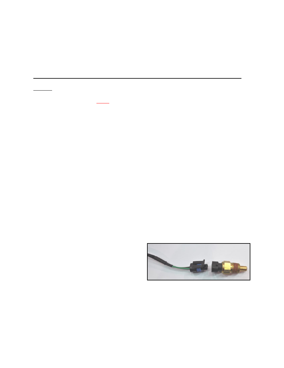
Remove the old temperature sensor and
install the provided 3/8-NPT Coolant
Temperature Sensor into the intake
manifold coolant port, as close as possible
to the thermostat. (This may require a
reducer bushing.)
o Connect the Green/Black wiring harness
from the throttle body to the coolant temperature sensor.
See Service Parts list on page
30
should the temperature sensor require replacement in the future.