Merit Medical Flex-Neck ExxTended Catheter User Manual
Page 4
When satisfactory locations for the exit-Site, circle , and the
arcuate bend are achieved, mark the secondary incision site,
rectangle . This is where the Tunneling Tool with the
attached exxTended catheter will temporarily emerge. With
proper implantation of the upper catheter segment, the black
marker ring will rest at the level of the secondary incision.
mark the exit cuff location, diamond . Trace the shape of
the arcuate tunnel path on the skin, using the Stencil cutouts
as a guide. The guidelines on Stencils l-1 and l-2 indicate the
planned pathway to connect the primary incision site, T-bar
and secondary incision, rectangle . See Figure 3.
Figure 3
upper chest stencil Instructions
note: The following Instructions are specific for implanting the
exxTended catheter on the patient’s left side. If the exxTended
catheter is to be implanted on the patient’s right side, substitute
the r-Series stencils.
align the midline edge of the l-1 Stencil on the patient’s abdom-
inal midline. adjust the Stencil caudally or cranially to position
the notched cutout on the upper border of the pubic symphysis.
This will be the location of the upper extent of the catheter coil
as it lies in the pelvis. See Figure 4.
Figure 4
With the Stencil aligned on the patient’s midline, and the
notched cutout positioned as above, mark the T-bar cutout
which indicates the location of the primary incision site through
which the lower catheter will be inserted during the implan-
tation procedure and specifies the final resting position of the
rectus cuff.
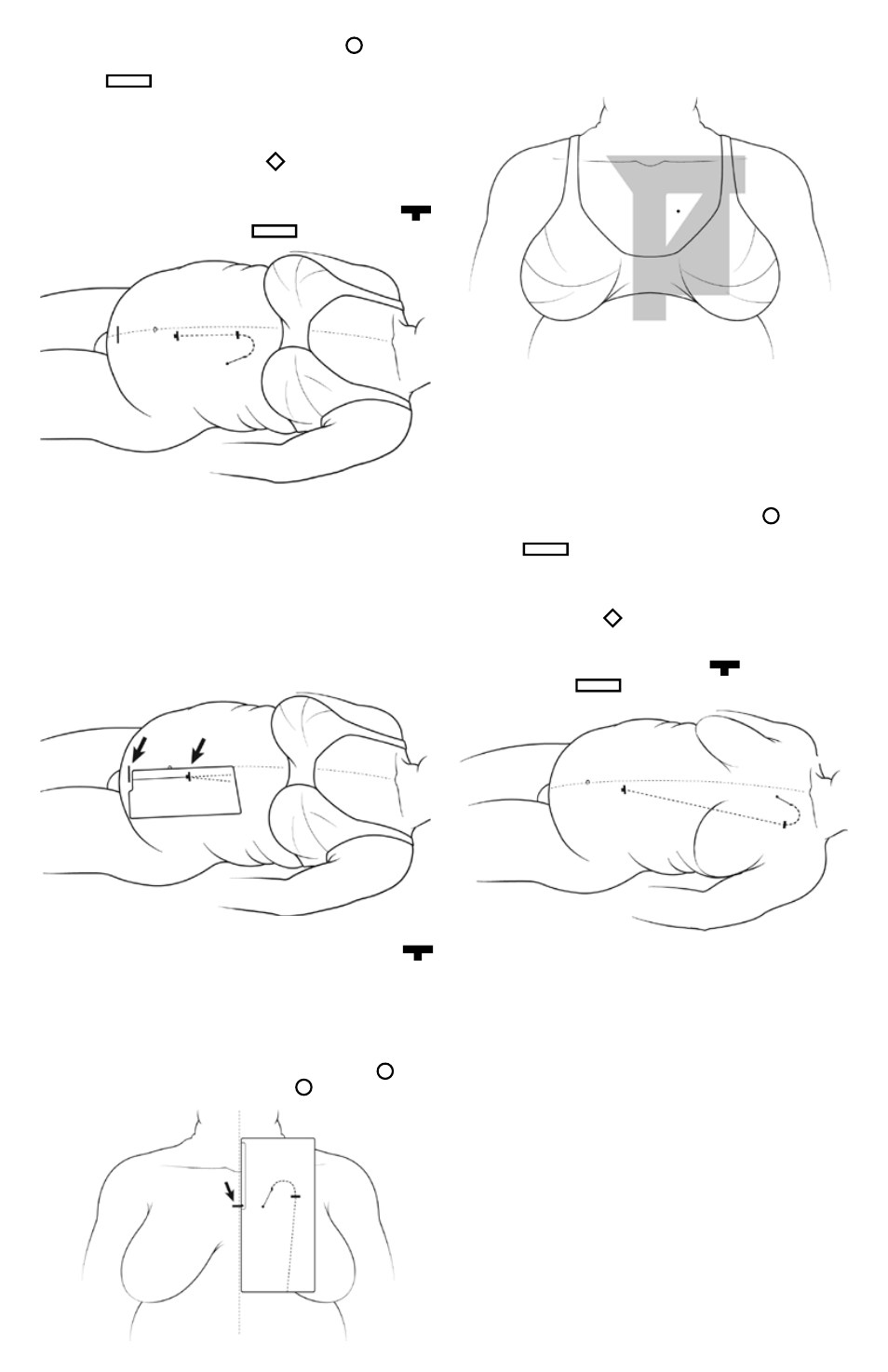
align the midline edge of the l-3 Stencil with midline of chest.
adjust the Stencil up or down until the exit-Site, circle , is in
desired position. mark the exit-site, circle . See Figure 5.
Figure 5
confirm that selected exit-site is free from open collar area ,
infraclavicular region, median sternotomy zone, and fleshy part
of breast . See Figure 6 for overlay of regions.
Figure 6
The midline edge of the Stencil should remain parallel to the
patient’s midline but may not exactly coincide with midline due
to lateral shift from weight of skin. confirm that the subcutane-
ous path indicated by the Stencil for the arcuate bend does not
conflict with the clavicle. If the subcutaneous path indicated by
the Stencil overlaps the clavicle, then shift the Stencil caudally
until the clavicle is cleared.
When satisfactory locations for the exit-site, circle , and the
arcuate bend are achieved, mark the secondary incision site,
rectangle . This is where the Tunneling Tool with the
attached exxTended catheter will temporarily emerge. With
proper implantation of the upper catheter segment, the marker
ring will rest at the level of the secondary incision. mark the exit
cuff location, diamond . Trace the shape of the arcuate tun-
nel path on the skin, using the Stencil cutouts as a guide. The
guidelines on Stencils l-1 and l-3 indicate the planned pathway
to connect the primary incision site, T-bar , and secondary
incision, rectangle . See Figure 7.
Figure 7
section B
exxtended™ loWer catheter ImPlantatIon for
uPPer aBdomen and uPPer chest exIt-sIte
Implanting the lower catheter
there are 3 options for implanting the lower catheter:
1. laparoscopic approach, with or without Y-Tec® catheter
implantation system. This approach is recommended. Y-Tec
peritoneal dialysis catheter implantation systems including In-
structions for use are available through merit medical Systems,
Inc.
note: If laparoscopy is used to implant the lower catheter,
deflate the abdomen before testing catheter patency to avoid
false fluid outflow rates.
2. open surgical dissection (cut-down technique).
3. percutaneous or modified Seldinger technique, with or
without fluoroscopic guidance.