Merit Medical Flex-Neck ExxTended Catheter User Manual
Page 3
marked by the Flex-Neck exxTended catheter Implantation
Stencils, in the clinic or during pre-op evaluation. at a
minimum, the patient should be evaluated preoperatively
to determine a proper, accessible location for the catheter
exit site. These marking should be noted for reference during
implantation.
3. The implanting physician should use the Flex-Neck exxTend-
ed catheter Stencils (included with each catheter pack) to verify
the primary implantation site, the upper catheter tunnel track,
and the exit-site, as previously chosen and marked in the clinic
or pre-op evaluation.
4. For upper chest catheter exit-site procedures, the implant-
ing physician will keep the subcutaneous part of the catheter
and the catheter exit-site off the sternum. doing so will protect
the integrity of the catheter in the event of future cardiovascular
surgery that may require a midline sternotomy.
outer
Inner
overall length,
Fill
diameter diameter
Straightened,
Volume
untrimmed
5.1 mm
3.5 mm
62.0 cm (lower cath)
maximum: 12.0 ml
62.0 cm (upper cath)
To find fill volume of
Must be trimmed to fit
trimmed, joined
patient physique and
catheter, multiply
exit-site location.
total length of joined
catheter (in cm) by
0.096 to get fill
volume in cc.
section a
InstructIons for flex-neck exxtended catheter
ImPlantatIon stencIl set
The Implantation Stencils for Flex-Neck exxTended peritoneal
dialysis (pd) catheters help choose the best implantation and
exit- sites for each patient. Note that these Implantation Stencils
cannot be used with other brands of pd catheters, or with other
sizes or styles of Flex-Neck pd catheters.
For best results, the Implantation Stencils can also be used
during operative preparations, to mark, coordinate, verify and/or
adopt the markings made during the preoperative examination
as needed after laparoscopic visualization of the peritoneal
space. please refer to the complete “Implantation Stencils for
Flex-Neck exxTended catheter Instructions for use” distributed
by merit medical Systems, for more information.
The Stencil pattern contains essential catheter design infor-
mation including the distance between the deep cuff and the
coil-tip, the shapes of preformed tubing bends, and the distance
between the superficial cuff and the exit-site. additional
features of the Stencil permit its precise orientation on the torso,
according to stable anatomical landmarks: the pubic symphysis,
representing the anterior cranial border of the deep pelvis, and
the anatomical midline of the torso. The Stencils permit accurate
and reproducible association of the catheter design elements
to these vital anatomical landmarks to help determine the
best catheter insertion site and deep cuff placement that will
produce the optimal pelvic position of the catheter coil and the
ideal exit-site location, either in the upper abdomen below the
costal margin, or in the upper chest off the sternum.
note:
each exxTended catheter kit includes three Stencils. each Stencil
has a reverse side for right (r) and left (l) catheter placements.
l-1, l-2 and r-1, r-2 are used for upper abdomen catheter
placement. l-1, l-3 and r-1, r-3 are used for upper chest
catheter placements.
cautIon
These exxTended Implantation Stencils are specific for oNlY
Flex-Neck exxTended adult peritoneal dialysis catheters.
• do NoT use these Stencils for other catheter brands.
• do NoT use these Stencils for Flex-Neck classic or arc™
catheters, in adult, adolescent, pediatric, or Infant sizes.
• do NoT resterilize these Stencils
• Stencils are available through merit medical Systems., Inc.
Patient marking in the surgical suite – upper abdomen and
upper chest
note:
These instructions are for marking the exxTended catheter
upper chest and upper abdomen configurations.
The following instructions are specific for implanting the
exxTended catheter on the patient’s left side. If the exxTended
catheter is to be implanted on the patient’s right side, substitute
the r-Series Stencils.
upper abdomen stencil Instructions
align the midline edge of the l-1 Stencil on the patient’s abdom-
inal midline. adjust the Stencil caudally or cranially to position
the notched cutout on the upper border of the pubic symphysis.
This will be the location of the upper extent of the catheter coil
as it lies in the pelvis. See Figure 1.
Figure 1
With the Stencil aligned on the patient’s midline, and the
notched cutout positioned as above, mark the T-bar cutout
which indicates the location of the primary incision site through
which the lower catheter will be inserted during the implan-
tation procedure and specifies the final resting position of the
rectus cuff.
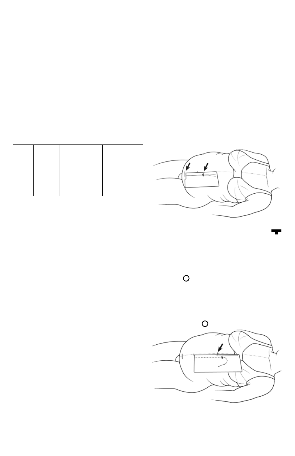
1. align the midline edge of the l-2 Stencil with the midline
of the patient’s abdomen. adjust the Stencil up or down until
exit-site circle cutout is in desired position according
to pre-procedural patient markings. confirm that the upper
edge of the catheter tunnel track, or arcuate bend, is below the
costal margin. If the subcutaneous path indicated by the Stencil
overlaps the costal margin, then shift the Stencil caudally until
the rib margin is cleared. The midline edge of the Stencil should
remain parallel to the patient’s midline but may not exactly
coincide with midline due to lateral shift from weight of skin.
mark the exit-site circle with the Stencil in this position.
See Figure 2.
Figure 2
confirm that selected exit-site does not conflict with belt line,
skin creases or folds. exit site should be easily visible to the
patient as indicated by pre-procedural consultation and
markings.