Installation instructions, Caution, Final assembly – GE PGP989SNSS User Manual
Page 30: Assemble burners, check ignition
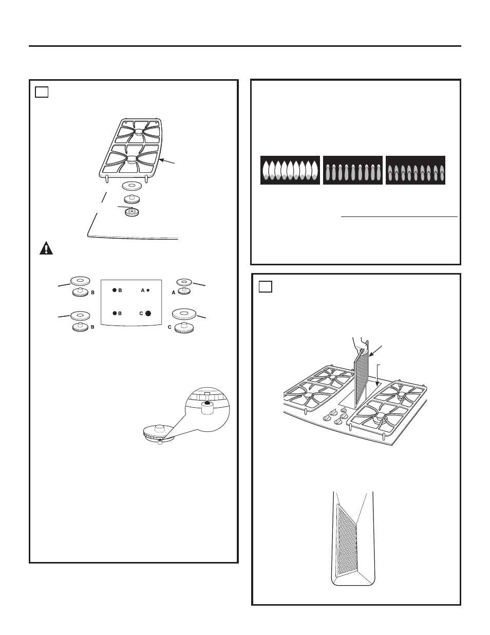
ASSEMBLE BURNERS, CHECK IGNITION
Assemble burner as shown.
CAUTION:
Do not operate the burner
without all burner parts in place.
Place the burner heads on the burner bases matching the
letters. Place the caps on the heads. Make sure that the
heads and caps are placed on the correct size burner. The
burner heads and burner bases
are labeled A, B and C to aid
reassembly. There is one small
(A), two medium (B) and one
large (C) head and cap.
Make sure the notch in the
burner head is positioned
toward the electrode. Rotate
the burner head around the burner base until it is level and
securely seated.
Place the grates over the burners.
Check for proper ignition:
• Push in one control knob and turn to LITE position.
• The igniter will spark and the burner will light; the igniter
will cease sparking when the burner is lit.
• First test may require some time, while air is flushed
out of the gas line.
INSTALL DOWNDRAFT FILTER,
VENT GASKET AND VENT GRILLE
Do not operate the vent without the filter in place.
• Place the filter diagonally through the vent opening.
• Make sure it rests, at an angle, on the supports in the
vent opening.
18
Installation Instructions
FINAL ASSEMBLY
19
Grate
Burner head
Burner cap
Electrode
Burner base
Curved side
toward the
center
30
Medium
Head
and Cap
Medium
Head
and Cap
Front of Cooktop
Small
Head
and Cap
Large
Head
and Cap
• Check to determine if your burner flames are normal. If
your burner flames look like A, turn off the burner and
make sure all parts are assembled correctly. Reassemble
and check. Normal burner flames should look like B or C
depending on the type of gas you use. With LP gas, some
yellow tipping on the outer cones is normal.
• Turn knob to OFF.
• Repeat the procedure for each burner.
A–Yellow flames B–Yellow tips
C–Soft blue flames
Call for service
on outer cones
Normal for natural
Normal for LP gas gas
Vent Filter
Vent
Chamber