Diagnosing array problems, Controller board runtime leds – HP Smart Array P600-Controller User Manual
Page 27
Diagnosing array problems 27
Diagnosing array problems
In this section
Controller board runtime LEDs.................................................................................................................. 27
Cache module LEDs................................................................................................................................ 28
Diagnostic tools ..................................................................................................................................... 29
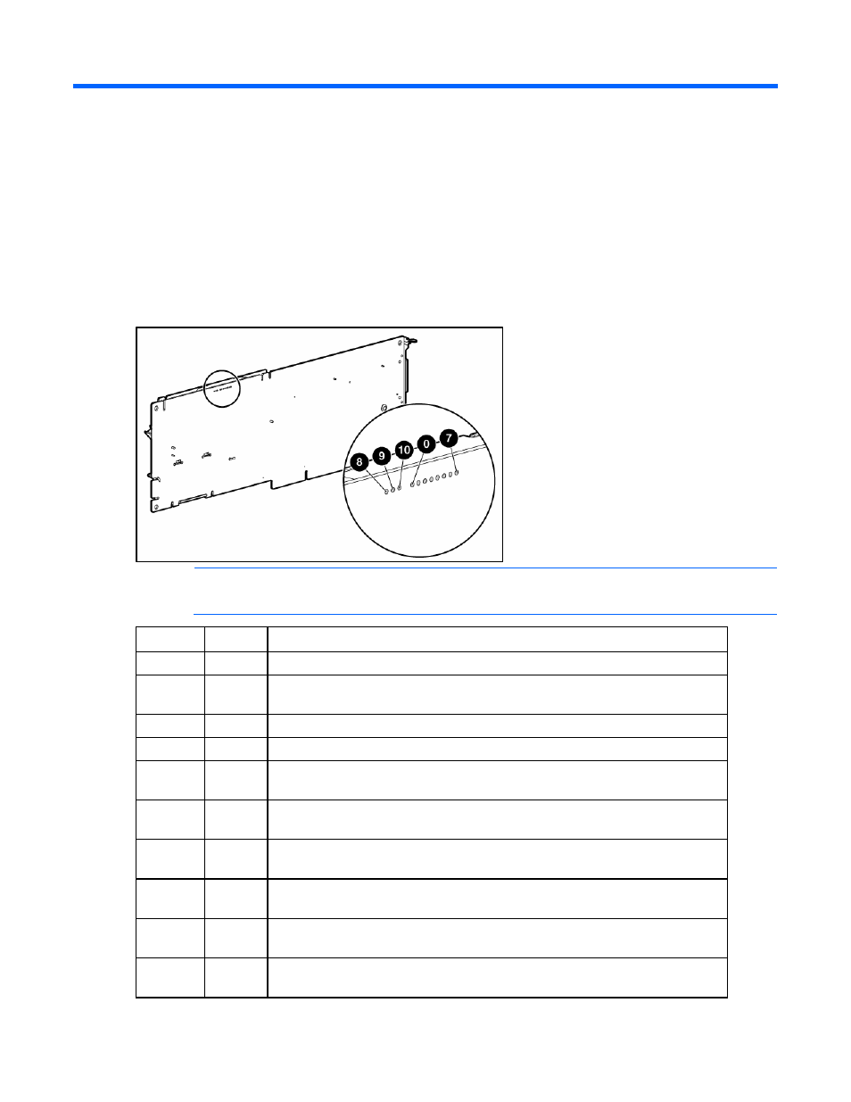
Controller board runtime LEDs
NOTE:
During server power-up, each runtime LED illuminates randomly until POST has
finished.
LED ID
Color
LED name and interpretation
0
Amber
CR510: Controller Failure LED. The controller firmware has detected an error.
1
Amber
CR511: Drive Failure LED. A physical drive connected to the controller has failed.
Check the Fault LED on each drive to determine which drive has failed.
2
Blue
CR512: Activity LED for SAS port 2I.
3
Blue
CR513: Activity LED for SAS port 1E and 1I.
4
Green
CR514: Command Outstanding LED. The controller is working on a command
from the host driver.
5
Blue
CR515: Heartbeat LED. This LED blinks every 2 seconds to indicate the controller
health.
6
Green
CR516: Gas Pedal LED. This LED, together with item 7, indicates the amount of
controller CPU activity. For details, refer to the following table.
7
Green
CR517: Idle Task LED. This LED, together with item 6, indicates the amount of
controller CPU activity. For details, refer to the following table.
8
Amber
CR507: Battery Status LED. For interpretation, refer to "Cache module LEDs (on
page
9
Green
CR508: Battery Charging LED. For interpretation, refer to "Cache module LEDs
(on page