Night Guard Home Surveillance System C3-RS-665 User Manual
Page 5
5
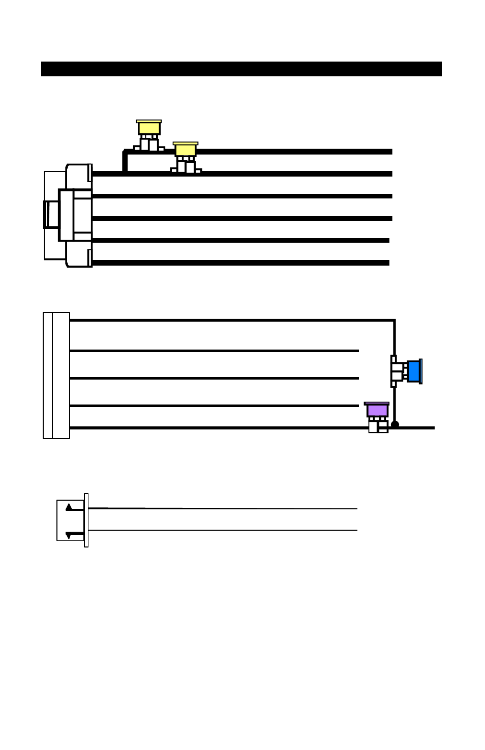
WIRE DIAGRAM:
#H1 6 PIN HEAVY GAUGE WIRE HARNESS
20A
20A
Red: Remote Start Power 1
Red: Remote Start Power 2
Violet: Starter (+) Output
Pink: Ignition 2 (+) Output
Yellow: Ignition 1 (+) Output
Brown: Acc/Heater (+) Output
#H2 5 PIN WIRE HARNES S
Red:
12v + Battery Power
Brown:
Siren (+) Output
Black:
System Main Ground (-)
White:
Parking Light Relay Output
Red/White:
Parking Light Relay Power Input
#H5. 3 PIN DOOR LOCK CONNECTOR
1. Blue Wire
3. Green Wire
( - ) Lock Pulse
( + ) Unlock Pulse
( - ) Unlock Pulse
(+) Lock Pulse