Specifications and ratings, 1 general specifications, 2 ratings and performance – TOHO ELECTRONICS TTM-00BT User Manual
Page 32
32
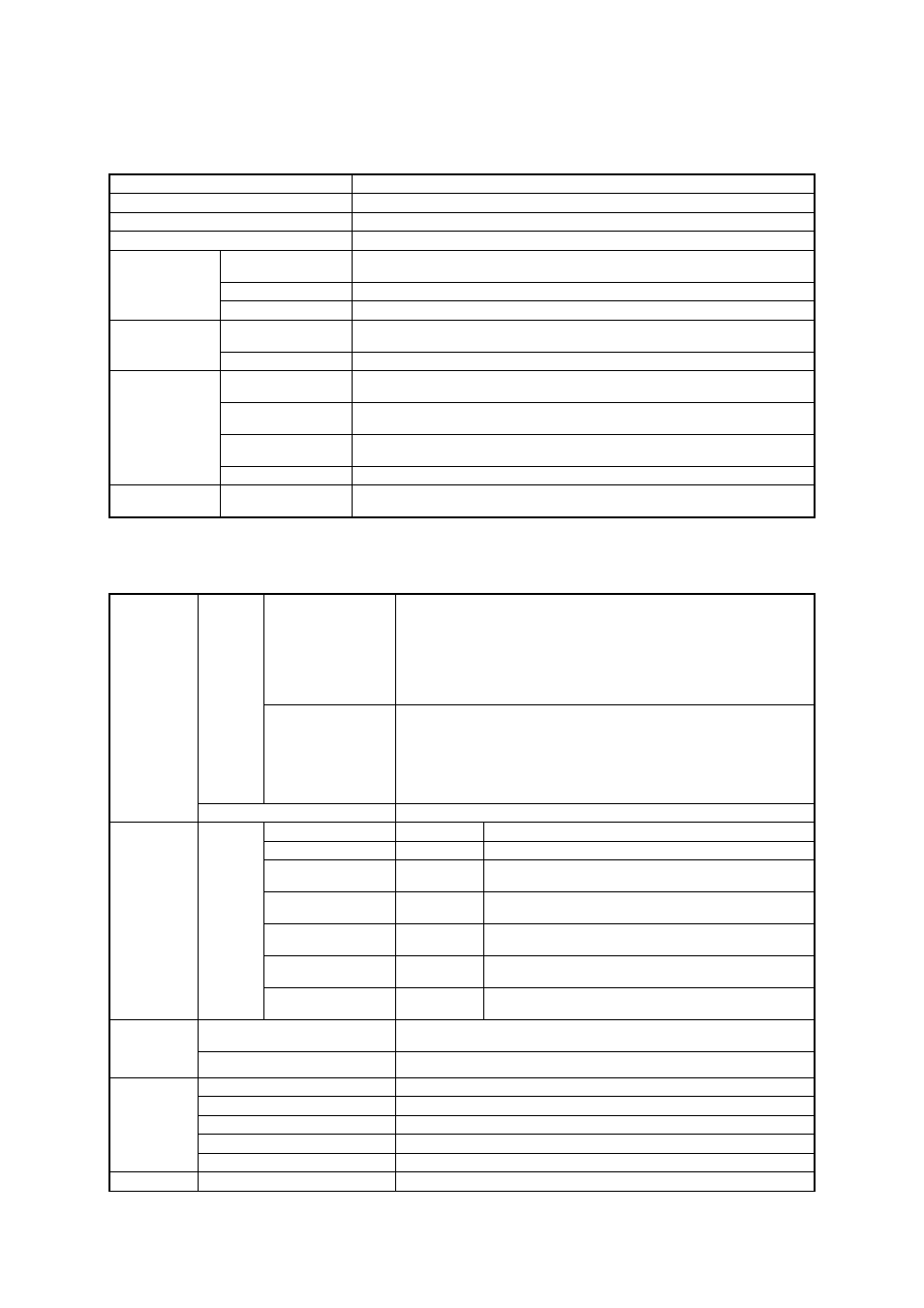
8. Specifications and ratings
8.1 General specifications
Power voltage
24V DC + 10% - 15%
Power consumption
8W or less
Insulation resistance
Between inputs and outputs, 500V DC, 20M
Ω
or more
Withstand voltage
Between inputs and outputs, 500V AC, 1 minute
Temperature/
humidity range
23
±
10C
°
/ 45 to 75%RH (non-condensing)
Power voltage
24V DC + 10% - 15%
Standard
environment
Vibration condition
0G
Temperature/
humidity range
-10 to 55
°
C / 35 to 85%RH (non-condensing)
Operating
environment
Power voltage
24V DC + 10% - 15%
Temperature/humidity
range
-20 to 65
°
C / 20 to 90%RH (non-condensing, non-freezing)
Vibration condition
0.5G (10 to 55Hz, 2 hours in each of the directions X, Y, and Z as installed on a
vertical panel)
Impact condition
0 to 50G (directions X, Y, and Z as installed on a vertical panel, with no continuous
impact)
Transportation/
storage
environment
Package drop
Drop height, 60cm (once each of the six sides, free fall without a rotary motion)
Machine
specifications
Weight
Approx. 450g
8.2 Ratings and performance
Thermocouple input
K and J switchover (JIS C 1602-1995)
Input resistance: 1M
Ω
or more
Effect of external resistance: 0.4
µ
V/
Ω
(0.01
°
C/
Ω
)
Burnout: Overdisplay
Measurement precision: Measurement ±(0.3% + 1 digit) or ±2
°
C, whichever
the larger
(to be specified under the standard environmental conditions, including the
cold contact compensation program)
Temperature
input
Input type
Resistance bulb input
Pt100/JPt100 switchover (JIS C 1604-1997)
External resistance: 0.2
°
C/
Ω
or less (per wire)
Burnout: Overdisplay
Bias current: approx. 2mA (flowing out of terminal A)
Measurement precision: Measurement ±(0.3% + 1 digit) or ±0.9
°
C,
whichever the larger
(to be specified under the standard environmental conditions)
Sampling period
200mS (at channel 8)
Power supply
LED3
Goes on when this product is on (green)
Control output
LED15 to 22
Goes on when the control output is turned on (red)
Temperature alarm
output
LED4 to 11
Goes on when the temperature alarm output is turned on
(red)
Heater wire break
alarm output
LED12
Goes on (red) when there is a heater wire break (there is no
output even if the output is turned on)
SSR breakdown alarm
output
LED13
Goes on (red) when there is an SSR breakdown (there is
output even if the output is turned off)
Error alarm output
LED14
Goes on (red) when there is a memory error, A/D error, or
sensor error
LED display
LED type
Communication
LED1
LED2
Blinks while receiving data (green)
Blinks while transmitting data (green)
Output in a special state
All outputs remain off for about 10 seconds after this product is turned on.
The control output is turned off when there is a measurement error.
Control
output/
temperature
alarm output
Open collector output
Output rating: 24V DC, 100mA (maximum) per point
Input voltage range
12 to 24V DC
±
10%
ON-state voltage
10.8V (min)
ON-state current
4mA (min)
OFF-state voltage
4V (max)
Voltage input
Minimum input time
500mS or more
CT input
±5% of the full span