Wiring diagram, Water control valve, Propor- tional valve flow sensor – Takagi T-M32 User Manual
Page 39
- 39 -
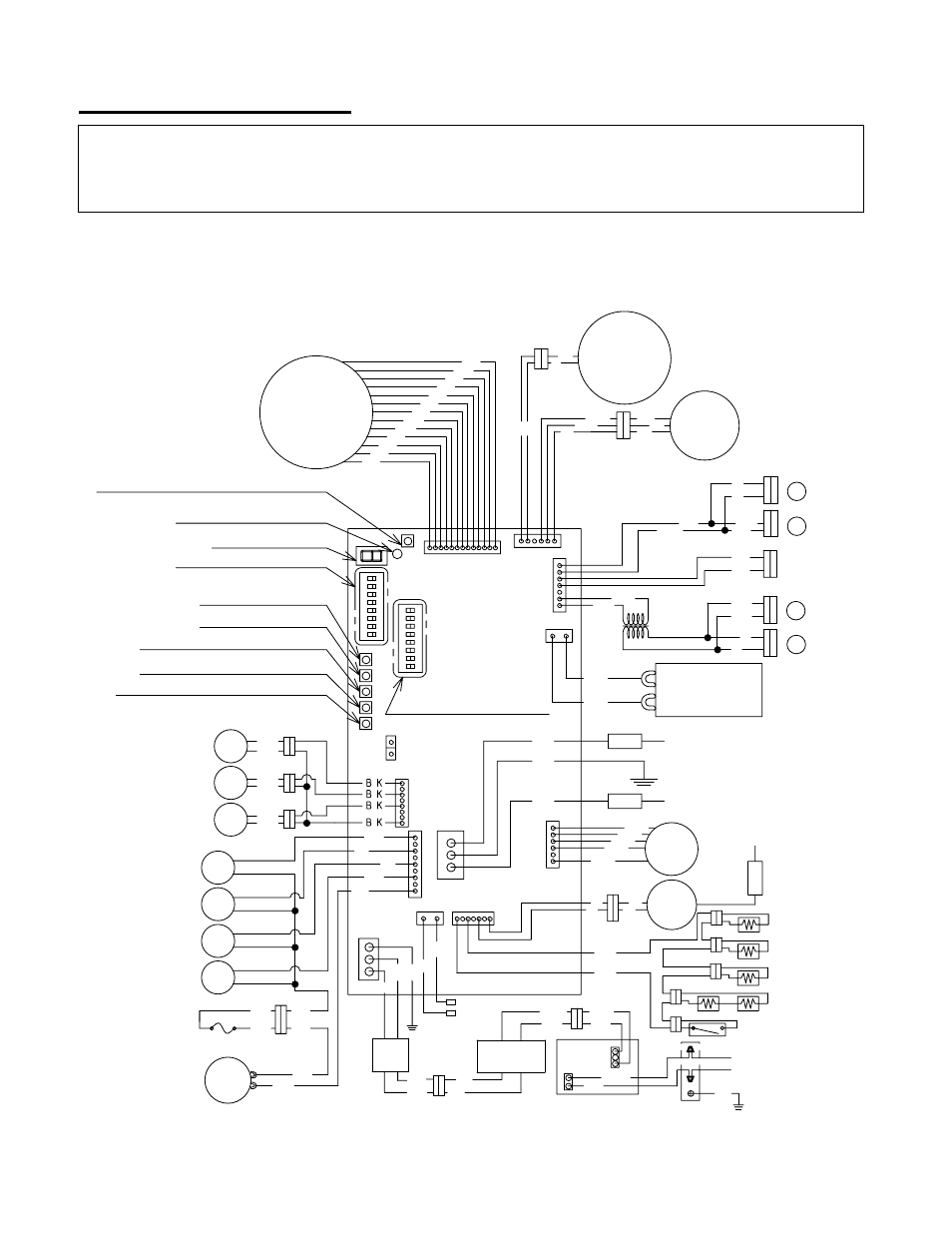
WIRING DIAGRAM
W: WHITE
R: RED
BK: BLACK
P: PURPLE
LB:LIGHT BLUE
BL: BLUE
G: GREEN
Y: YELLOW
O: ORANGE
BR:BROWN
GY:GRAY
Inlet
thermistor
Output
thermistor
Mixing
thermistor
B K
B K
B K
H i -
l i m i t
Air-fuel
ratio rod
Ground
Flame rod
MV
SV3
SV1
SV2
F M
Elect rod
I G
R
Y
G
W
B K
B R
R
O
Y
G
W
B K
B L
Water
Control
valve
O.H.C.F
B L
B L
B L
B L
Y
G
O
R
B L
Y
O
W
P
P
P
P
Propor-
tional
Valve
Flow
Sensor
W
R
B K
W
R
WR
B K
R
W
B L
B L
B L
L B
G
O
R
Master
W
W
B K
B K
B L
B L
R
R
Remote
controller
port
W
B K
Heater
Thermostat
Heater
B K
B K
G
W
B K
Trans-
former
Ground
B R
B R
AC120V
G
Ground
B K
W
W
B K
B R
B R
Fuse
box
W
BK
Heater
1
23
4
5
6
OF
F
7
8
G F I
12
3
4
56
OF
F
7
8
B K
W
Pump
Heater
2
1
G Y
G Y
P
P
O
O
3
4
7 S e g L E D
D i p s w i t c h
( A d j u s t a b l e )
D i p s w i t c h
( u n t o u c h a b l e )
M A X b u t t o n
M I N b u t t o n
I n c r e a s e b u t t o n
D e c r e a s e b u t t o n
E r r o r c a l l b u t t o n
B u r n i n g l a m p
Number display button
A wiring diagram is located on the inside front panel of the appliance.
Electrical Rating: 120 VAC, 60 Hz.
Note: If any of the original wiring supplied with this appliance must be replaced, it must be replaced with
appliance wiring material (180c) or its equivalent. Wires are available through the manufacturer.