0 operation, 2 electrical termination – Setra System Model 231 User Manual
Page 9
9
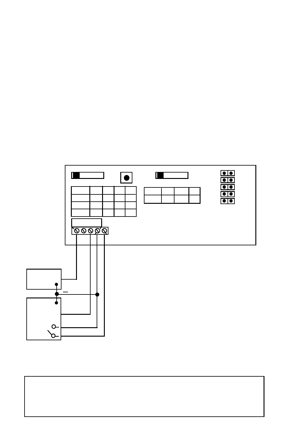
4.2 Electrical Termination
Wiring: 3-Wire, 0 to 5, 0 to 10, 1-5 VDC and Remote Zero
The Model 231 when configured for voltage output is a 3-wire circuit device with
three terminals available for wiring. The -Excitation and -Output are commoned
on the circuit.
The 231 can operate from 12-30 VDC (18-28 VAC) nominal output power supply.
Note: The Zero terminals, connected to digital output, provide a contact closure relay for automatic reset to zero pressure
by the monitoring system. CAUTION: ZERO input is for dry contact, do no apply voltage to ZERO Terminals
The optional remote zero is a normally open relay wired between COM and
REMOTE ZERO terminals. In order to initiate ZERO function the relay contact shall
be closed.
Figure 5
A
B
C
D
MS1
50 25 10
5
MS2 100 50 20 10
MS3 250 125 50 25
A B C D
RANGES
ZERO
OUTPUT
A
B
C
D
4-20 0-5 0-10 1-5
A B C D
BAR
A.REV
SLOW
BI-DIR
SWAP
PSI
NORM
FAST
UNI-DIR
NORM
+
-
+
EXC.
COM
OUT
DC/AC
Power Supply
Controller
+
+
Installation of the Model 231 is now complete.
Important: Prior to putting the unit into service, press the “Zero” button,
then use the “Range Selection Switch” to select a range. After selecting a
range, press the “Zero” button again. For instructions regarding operation
of the Model 231, please refer to Section 5, page 10.
Voltage
Relay