2 electrical termination, Wiring: 2-wire , 4 to 20 ma and remote zero, 0 electrical installation – Setra System Model 231 User Manual
Page 8
8
4.0 ELECTRICAL INSTALLATION
To access the electrical connections, turn the screws on the top of the case
counter clockwise until the hinged cover can be flipped up. The screws are
captured and secured in the cover. Wiring is through the 1/2” conduit opening.
Both current and voltage outputs are reverse wiring protected.
Note: The Zero terminals, connected to digital output, provide a contact closure relay for automatic reset to zero pressure
by the monitoring system. CAUTION: ZERO input is for dry contact, do no apply voltage to ZERO Terminals
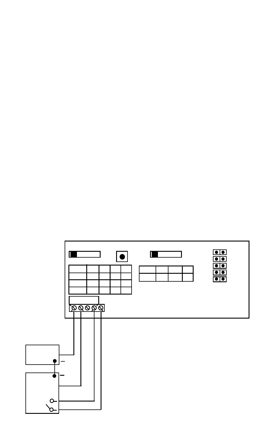
4.1 Electrical Termination
Wiring: 2-Wire - 4 to 20 mA (Current Output) and Remote Zero
Model 231 when configured as a current output transducer is a true 2-w
ire, 4-20 mA current output device and delivers rated current into any external
load of
0-1000 ohms.
When configured as a 4-20 mA current output device the current flow is in one
direction only. PLEASE OBSERVE POLARITY.
We suggest that an electrical cable shield be connected to the system’s loop
circuit ground to improve electrical noise rejection.
Min. Supply Voltage:
12 + .02 x (Resistance of receiver plus line)
Max. Supply Voltage:
30 + .004 x (Resistance of receiver plus line)
The optional remote zero is a normally open relay wired between COM and
REMOTE ZERO terminals. In order to initiate ZERO function the relay contact shall
be closed.
A
B
C
D
MS1
50 25 10
5
MS2 100 50 20 10
MS3 250 125 50 25
A B C D
RANGES
ZERO
OUTPUT
A
B
C
D
4-20 0-5 0-10 1-5
A B C D
BAR
A.REV
SLOW
BI-DIR
SWAP
PSI
NORM
FAST
UNI-DIR
NORM
+
–
EXC.
COM
OUT
DC Power Supply
Controller
Current
(4-20 mA)
+
Figure 4
+
–
+
Relay