Electrical data – Setra System Model ASM User Manual
Page 3
3
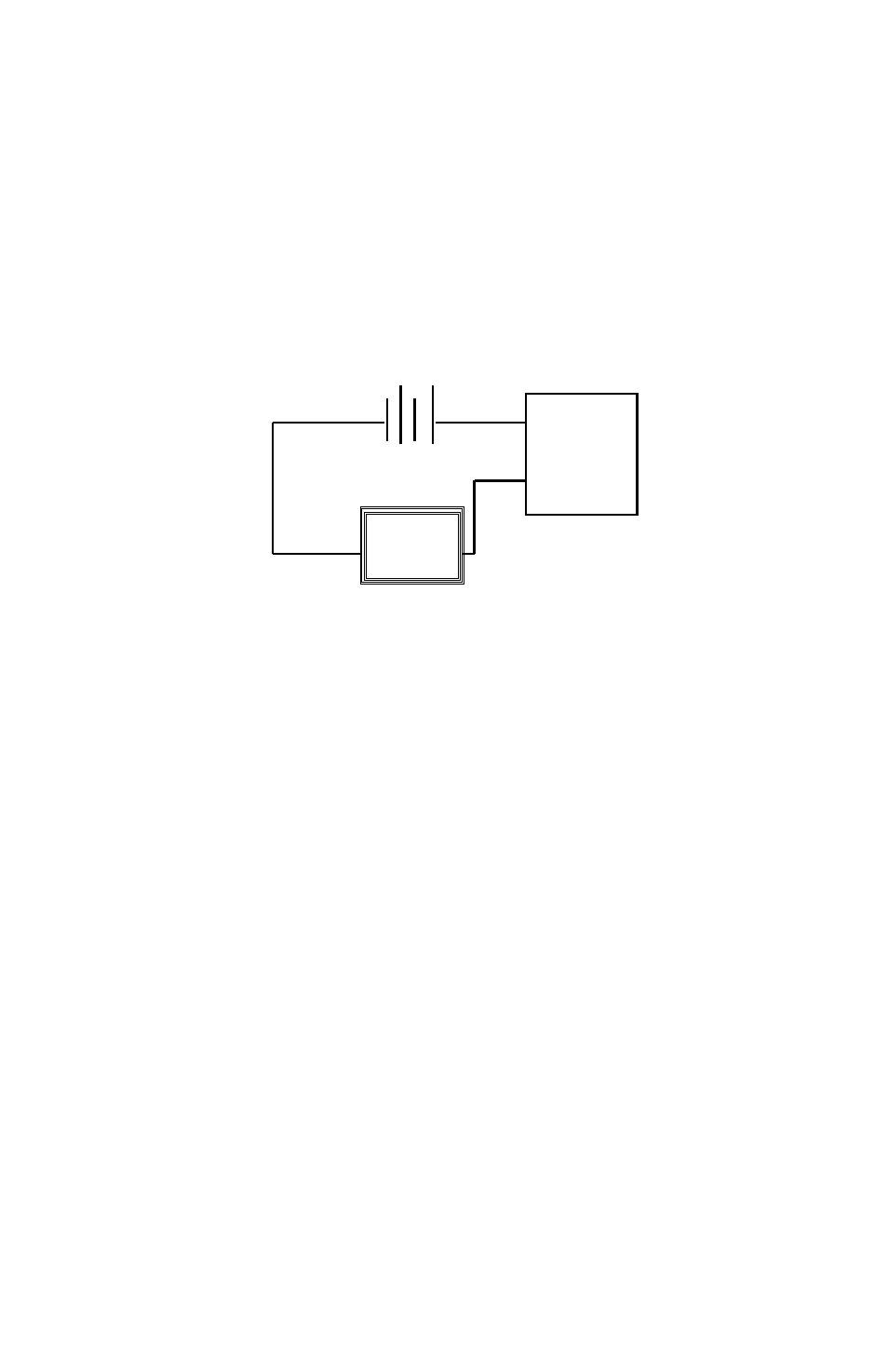
The current flows into the +EXC terminal and returns back to the power sup-
ply through the -EXC terminal (See Diagram 1). Note: The +SIG Out and -SIG
Out terminals are not used. The power supply must be a DC voltage source
with a voltage range between 9 and 30 VDC measured between the + and
- terminals. The unit is calibrated at the factory with a 24 VDC loop supply
voltage.
3.4 Cable for Bayonet Connectors
For good EMC performance, shielded cable shall be used and grounded to
earth ground. Cable shall only be used within a building and not be longer
than 30 m (100 ft.).
Diagram 1
Electrical Data
Signal Output Ranges
0-5 VDC, 0-10 VDC (4-wire); 4-20mA (2-Wire)
Nominal Excitation
24 VDC
Excitation Range
9-30 VDC (5 VDC & 4-20mA output)
15-30 VDC (10 VDC Output)
Current Consumption
<23mA
Circuit Response Time
<10ms (Voltage Version),
<80ms (4-20mA Version)
Warm-up, Environmental
Within +/-0.02%FS after 15 min. Warm-up Time
Miswiring
Reverse Excitation Protection
4.0. CALIBRATION
The ASM transducer is factory calibrated and should require no field adjust-
ment if mounted in a vertical position. Whenever possible, any zero and/or
span offsets should be corrected by software adjustment in the user’s control
system. However, fine zero and span adjustments can be made through use
of Secure-Cal
TM
accessory (purchased separately) for calibration access. The
Model ASM transducer zero offset is trimmed in the vertical position (pressure
port pointing downward) prior to shipping from factory.
4.1 Zero/Span Adjustments with Secure-Cal
TM
To make secure zero and span adjustments, attach SecureCal
TM
accessory to
ASM pressure transducer. (See Diagram 2).
+
_
9 to 30 VDC
ASM
Current
Monitoring
Device