Reserved for communication with securecal, Calibration module – Setra System Model ASM User Manual
Page 2
2
2.4 Installation of Pressure Fittings
Your transducer is designed for the most accurate operation when subjected
to pressures within the designated pressure range. Refer to page 4 for proof
pressure limits.
Standard sealants such as Teflon pipe tape generally are satisfactory on NPT
threads. For the most sensitive pressure ranges, excessive high torquing of a
metal pressure fitting may cause slight zero shift which may be trimmed out
using the zero adjustment. Use of a plastic fitting often shows no noticeable
zero shift. The torquing effect does not appreciably affect linearity or sensitiv-
ity. The 3/4 in. wrench flat (Hex) on the unit must be used when installing the
positive pressure fitting.
3.0 ELECTRICAL INSTALLATION
3.1 Electrical Connections
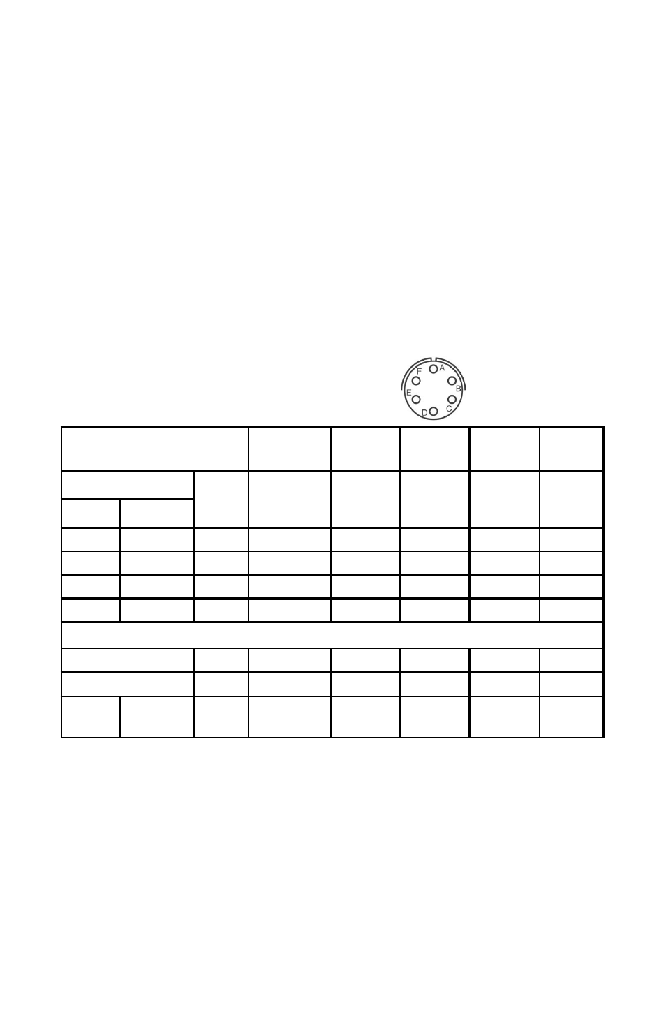
ASM is available with a cable, or bayonet connector options having different
connector pin-outs shown in table below:
Code B3
(Standard)
Code B4
Option
Code B5
Option
Code B6
Option
Code B7
Option
Electrical Connection
Wire
Color
Bayonet
Conn.
Pinout
Bayonet
Conn.
Pinout
Bayonet
Conn.
Pinout
Bayonet
Conn.
Pinout
Bayonet
Conn.
Pinout
Current
Voltage
+EXC
+ EXC
Red
A
A
A
C
A
-EXC
- EXC
Black
D
B
B
D
C
NA
+ Sig Out
Green
B
C
D
A
F
NA
- Sig Out
White
C
D
C
B
E
Reserved for communication with SecureCal
TM
calibration module
SecureCal
Blue
E
E
E
E
B
SecureCal
Brown
F
F
F
F
D
Shield
Drain Wire
Ex-
posed
Case
Case
Case
CAUTION: Connecting -EXC to positive excitation and +Sig to negative excita-
tion at the same time may damage the unit.
3.2 Voltage Output Units
The Model ASM voltage units are a four-wire type circuit energized thru +EXC
and -EXC terminal with 0-5VDC or 0-10VDC analog output through the +SIG
Out and -SIG Out terminals.
3.3 Current Output Units
The Model ASM current units are a two-wire loop-powered 4 to 20mA current
output and deliver rated current into any external load of 0 to 800 ohms.
Connector
Viewed from Front