3 rs-485 network design and installation, 4 dimensional drawings, 3 junction box for rs-485 networks – ROTRONIC HC2 User Manual
Page 17: Junction box for rs-485 networks, E-m-hc2-accessories_24
E-M-HC2-accessories_24
Rotronic AG
Bassersdorf, Switzerland
Document code
Unit
Accessories and Parts
for probes, indicators and transmitters
Instruction Manual
Document Type
Page 17 of 23
Document title
© 2009-2010; Rotronic AG E-M-HC2-accessories_23
7.2.3
RS-485 network design and installation
Please follow the instructions provided in document E-DV04-RS485.01
o
Limit the RS-485 network to a single main data line (one segment)
o
Terminate each end of the main data line with a 240 Ohm resistor. Termination resistors should be placed
only at the extreme ends of the data line, and no more than two terminations should be placed in any
single segment of an RS-485 network
o
The total length the T connections should be included in the limit set for the main data line
(100 m or 1000 m)
o
Do not connect more than 64 devices to the same main data line
o
Each device connected to the RS-485 network should be given a unique address (1 to 64)
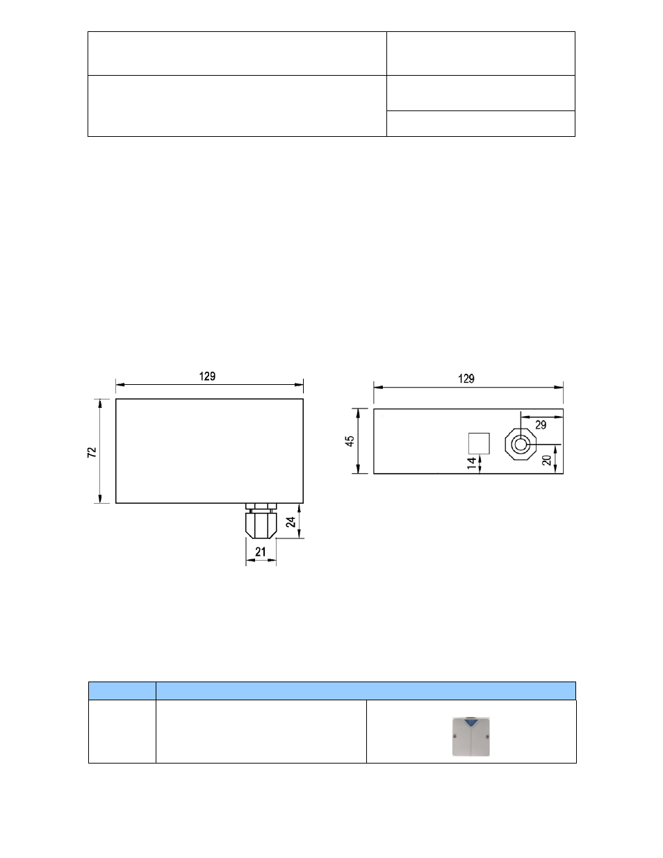
7.2.4
Dimensional drawings
7.3 Junction box for RS-485 networks
The AC3021 is a wall mounted junction box designed to facilitate the connection of devices to a RS-485 main
data line.
Order Code Description
AC3021
Passive junction box for RS-485 networks,
designed for wall mounting
RJ45
Dimensions in mm