ROTRONIC RS24T User Manual
Page 11
E(D/F)-M-RS12/24T-V1_00
Rotronic AG
Bassersdorf, Switzerland
Document code
Unit
Ventilierter Wetterschutz
Ventilated weather and radiation
shield
Instruction Manual
Document Type
Page 11 of 17
Document title
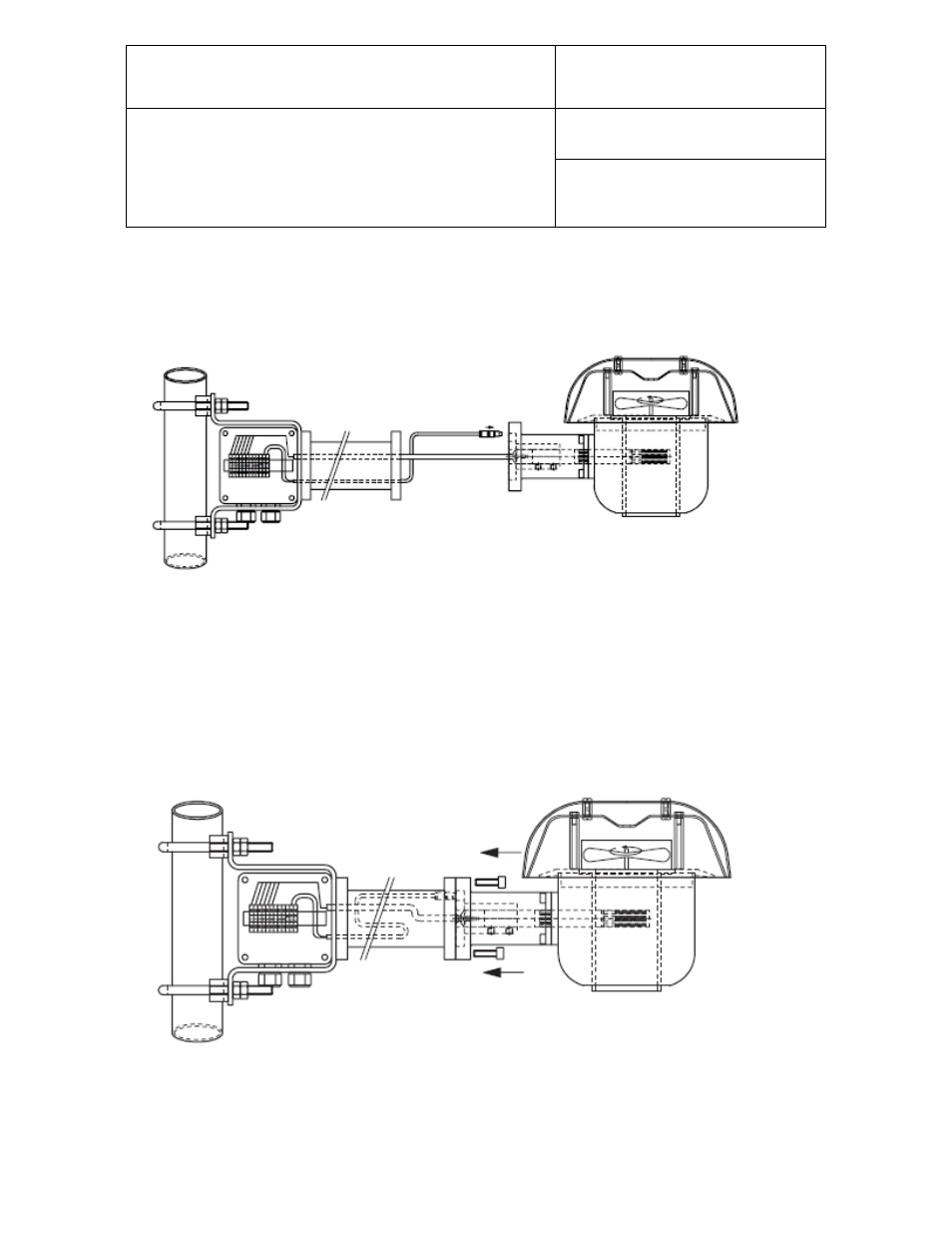
5.2 Assemble the adaptor, probe and weather protection shield. Make sure to position the slot
for the fan connector correctly. If positioned correctly, adaptor and flange form an even
surface. The adaptor must not be fixed by screws. Two ball-type locks fix the adaptor in its
position.
5.3 Join the connectors of the probe and mounting arm. The small two-pin connector serves for
the fan supply. For probes without plugs: Loop the cable into the connection box and wire
according to the schematics. The wire colours are mentioned on every schematic
accompanying the probes. Push a surplus length of cable back into the tube.
5.4 Align the two sub-assemblies and tighten the screws. Mounting onto the pole may be done
at any time; either before or after assembly.
.5 When disassembling, make sure that a cable probe (MP102H or MP402H) is disconnected
in the junction box before the screws between shield and mounting arms are removed.