3 logical inputs (on / off), 4 pin-out diagrams, 5 operating limits – ROTRONIC Dockingstation with WEB-Server User Manual
Page 5: Logical inputs (on / off), Pin-out diagrams, Operating limits, In-e-ds-u4web-v1_14
IN-E-DS-U4WEB-V1_14
Rotronic AG
Bassersdorf, Switzerland
Document code
Unit
Docking station DS-U4WEB with web
server version 1: instruction manual
Instruction Manual
Document Type
Page
5 of 15
Document title
© 2007; Rotronic AG
IN-E-DS-U4WEB-V1_14
2.3 Logical inputs (on / off)
Several models of docking station allow the HygroLog NT to process up to 2 logical inputs.
Typically this is used to monitor a relay contact, a door contact, etc.
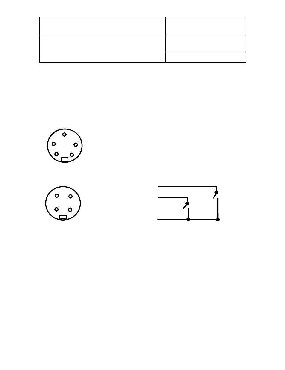
2.4 Pin-out diagrams
Logical Thresholds: logical 1:
≥ 2.8 VDC, logical 0: ≤ 0.7 VDC
2.5 Operating limits
The docking station operating limits are the same as for the HygroLog NT data logger:
HygroLog NT without display:
● -10…50°C with the factory supplied alkaline battery
● -30…70°C with a lithium battery or an external AC adapter
HygroLog NT with display:
● -10…50°C with the factory supplied alkaline battery
● -10…60°C with a lithium battery or an external AC adapter
The HygroClip probes have generally wider operating limits (see individual probe specifications).
4
3
2
1
Logical inputs - solder side of matching male connector
1: + 3.5 VDC
2: Input 1
3: Input 2
4: GND
1
2
GND: not used (eventually use for a shield)
+3.5 V
Note: an internal pull-down resistor sets
each input to 0 when the contact is open.
3
5
4
2
1
Inputs 4, 5, 6 and 7 - solder side of matching male connector
1: not used
2: power (DC+)
3: GND (docking station) / analog (-)
4: DIO
5: analog signal (+)