Dwyer Mark User Manual
Page 20
19
WIRING PROCEDURE: GENERAL
• Complete all electrical wiring in accordance with Local and National Electrical Codes by qualified personnel
• It may be necessary to segregate power and signal circuits in separate conduit entries.
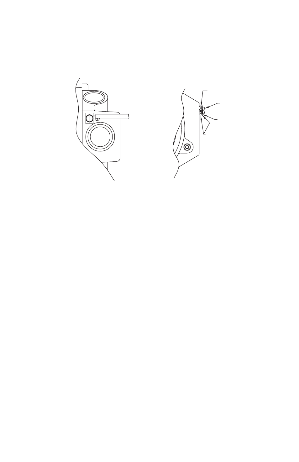
• For units supplied with both internal ground and external bonding terminals, the ground screw inside the housing
must be used to ground the control. The external bonding screw is for supplementary bonding when allowed or
required by local code. When external bonding conductor is required, conductor must be wrapped a minimum of
180° about the external bonding screw. See below.
• Products with flying leads shall be terminated in approved junction box.
WIRING PROCEDURE: HAZARDOUS LOCATIONS, FLAMEPROOF CABLE CONNECTION:
• The cable entry device shall be certified in type of explosion protection flameproof enclosure “d” suitable for the
conditions of use and correctly installed.
• For ambient temperatures above 60°C, cables and cable glands suitable for at least 95°C shall be used.
CONDUIT CONNECTION:
• An Ex d, EEx d or UL and/or CSA (with appropriate classes and groups) certified sealing device such as a conduit
seal with setting compound shall be provided immediately following the conduit entrance to the enclosure. UL &
CSA listed factory sealed leads are provided from the factory on request.
• For ambient temperatures above 60°C, the wiring and setting compound in the conduit seal shall be suitable for
at least 95°C.
• Degree of protection IP66/68W is maintained when suitable glands/plugs are used.
WIRING PROCEDURE: HAZARDOUS LOCATIONS, INTRINSIC SAFETY
• Potentiometer, Transmitter and each Switch and/or NAMUR Sensor must be treated as separate intrinsically safe
circuits.
ELECTRICAL RATINGS:
• Potentiometer, see page number 4.
• Transmitter, see page number 4
• Switches, see model chart on page number 5.
INTRINSIC SAFETY INPUT PARAMETERS: (SUFFIX “IS” & II)
• Potentiometer, Ui = 30V; Ii = 50mA; Pi = 0.65W.; Li = 0µH; Ci = 0nF.
• Transmitter, Ui = 30V; Ii = 100mA; Pi = 1.3W; Li = 0µH; Ci = 0nF.
• Switches, Ui = 30V; Ii = 100mA; Pi = 1.3W; Li = 0µH; Ci = 0nF.
• Namur Sensor, Ui = 16V; Ii = 76mA; Pi = 242mW; Li = 50µH; Ci = 40nF.
• Transmitter with HART
®
communication, Ui = 30V; Ii = 100mA; Pi = 1.3W; Li = 0µH; Ci = 4nF.
CONDUCTOR
SCREW
LOCKWASHER
CLAMP