Dwyer Mark User Manual
Page 11
10
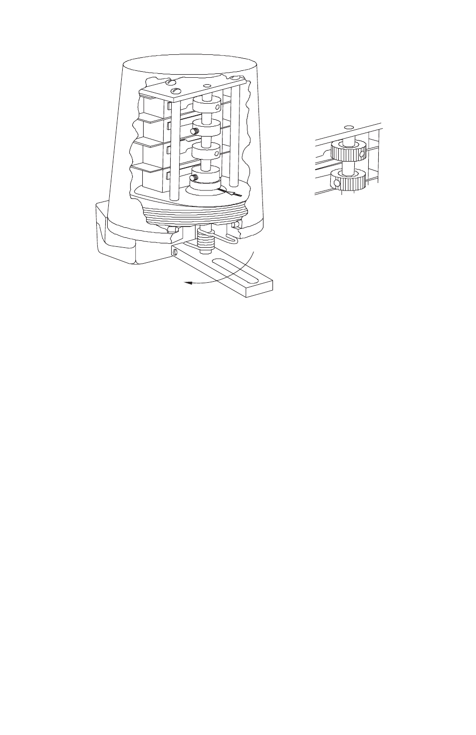
MARK 1 AND 4 LEVER DRIVE INSTALLATION
1
2
3
4
3
4
CLOCKWISE
INSTALLATION PROCEDURE
1. Attach proper mounting bracket to switch housing using screws provided. Tubular spacers are provided for some
installations.
2. Attach appropriate driving lever onto shaft. Do not tighten.
3. Attach switch and bracket to actuator, making sure that lever is free to rotate over entire range of actuator stroke.
4. Attach driving pin or bolt through lever arm if slotted, or on driving side of solid lever. (It may be necessary to loosen
or remove mounting bracket to accomplish connection on some actuators.)
5. Operate actuator very slowly and observe movement of all pins and levers to be sure there are no interferences.
Slide lever up or down on switch shaft to most desirable position. When all motions are made and clearances are
adequate, tighten clamp screw on lever that was left loose in step 2. Tighten all mounting screws. Recheck the
travel of all levers and pins for proper clearance through the entire stroke of the actuator.
6. Unscrew cover. Keep threads clean and free from damage. Index marks are imprinted into driven magnet collar as
shown (Mark 1 only). Set screws or holes in manual cams (#2, 4 and 6) will be directly above index marks on those
switches that are Closed. Marks must be in line when making switch cam adjustments. Cams are set at factory
when in the counterclockwise position, as shown, and listed as follows:
2 Switch Unit
#1 Open
#2 Closed
4 Switch Unit
#1, 3 Open
#2, 4 Closed
6 Switch Unit
#1, 3, 5 Open
#2, 4, 6 Closed
90º travel in clockwise direction will reverse all of above switch positions.