Dwyer Mark User Manual
Page 17
16
CALIBRATION
A. Set the valve at the position where you want the meter to read 0% (that is 4 mA). It may be necessary to move the
plug connector to change the direction of current output to increasing for clockwise rotation or vice versa.
B. On models 15XXX, loosen the two bottom set screws on the coupling. Rotate the coupling and potentiometer shaft
to the position where the meter reads 0% (4 mA). Tighten two set screws.
C. Turn valve to opposite position where meter should read 100% (20 mA). Use small screwdriver to adjust the blue
rectangular potentiometer "span" until 100% (20 mA) is on the meter. If it is not possible to reach 100%, refer to
Troubleshooting instructions.
D. Return valve to original position at 0% (4mA). Use small screwdriver to adjust "zero" turning until 0% (4 mA) is read
on meter. Repeat steps C & D until 4 and 20 mA read consistently on each end of stroke.
TROUBLESHOOTING
I. If no current flows, check polarity of current loop (plus and minus screws on terminal strip). Also check loop
resistance for open line.
II. If full output current cannot be achieved by adjustment, voltage at transmitter may be too low. If so, increase power
supply voltage until a minimum of 15 volts is registered or move voltage shunt to 12 VDC.
III. If current increases and decreases in the wrong direction, move the plug Connector from CW to CCW or vice versa.
IV. Check specs to make sure you are in range of adjustment, (See chart on previous page).
V. If the zero adjustment does not have enough range, the zero must be mechanically realigned as follows: Set the
“zero” (fine 4 mA) adjustment to the middle of its range. (Full multi-turn range is 25 revolutions; set at 12-1/2
revolutions.) Repeat calibration steps B, C and D.
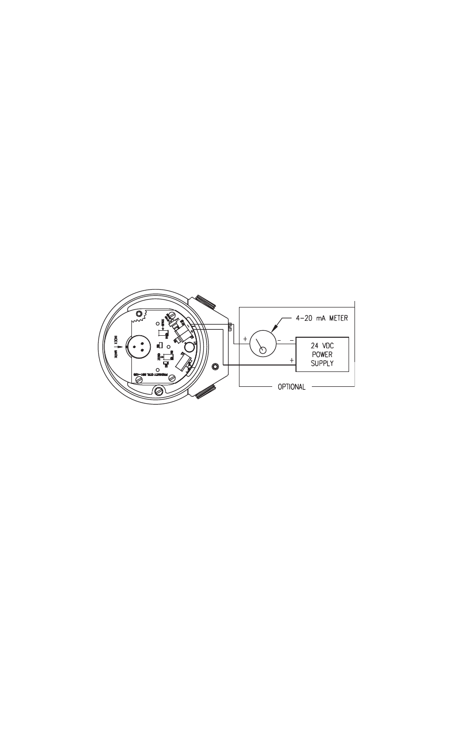
Two Wire Connections
See Pages 19-25 for wiring procedure, intrinsic safety parameters, relevant warnings and schematics.