Dwyer IEFS User Manual
Page 7
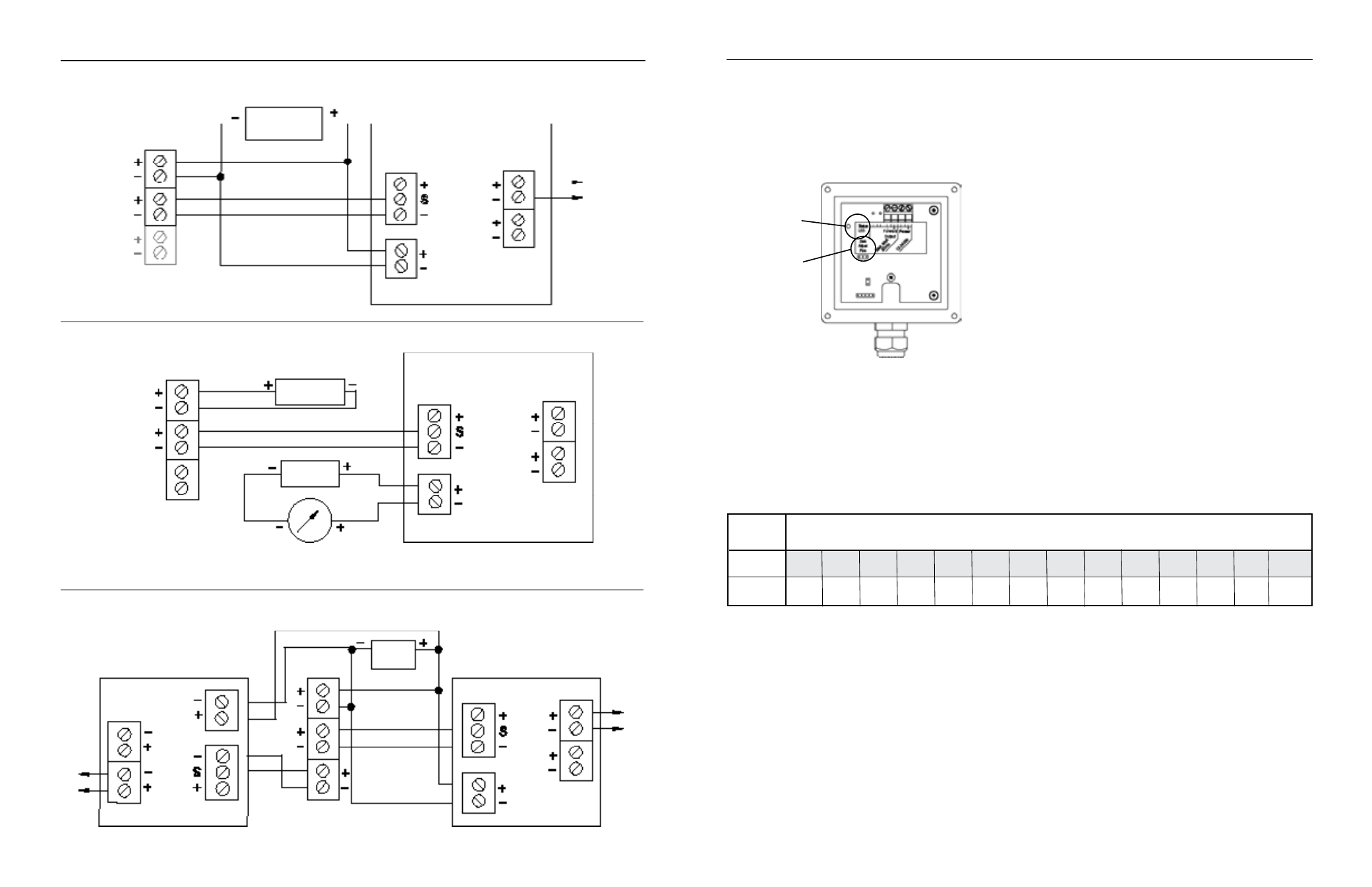
CONNECTIONS DIAGRAMS
SERIES RTI DISPLAy AND PROPORTIONAL FEED
Sensor
Input
Power
Forward Output
SERIES IEFS
24 VDC Power
Power
4 to 20mA
Pulse
Scaled
Pulse
Pass-Thru
To
Proportional
Feed
Metering
Pump
SERIES RTI DISPLAy AND 4 to 20 mA OuTPuT
SERIES RTI
*See Dual RTI Diagram for an
example of bidirectional connections.
*See Dual RTI Diagram for an
example of bidirectional connections.
Page 10
Page 11
Reverse Output
(-RFO only)
IEFS SERIES
DuAL SERIES RTI DISPLAyS
(Example of bidirectional Connection)
Power
Forward Output
Sensor
Input
24 VC
Power
Power 4 to 20mA
Pulse
Scaled
Pulse
Pass-Thru
SERIES RTI
SERIES RTI
Sensor
Input
Power 4 to 20mA
Pulse
Scaled
Pulse
Pass-Thru
Reverse Output
(-RFO only)
Reverse Output
(-RFO only)
Power
Forward Output
SERIES IEFS
4 to 20 mA Device
(e.g. pump, PLC)
24 VDC
Power
Sensor
Input
Power
4 to 20mA
Pulse
Scaled
Pulse
Pass-Thru
SERIES RTI
24 VD-
CPower
Min 0.28
Max 20.0
FLOW RATES (IN GALLONS PER MINuTE)
Feet Per
Second
NOMINAL PIPE SIzE
3” 4” 6” 8” 10” 12” 14” 16” 18” 20” 24” 30” 36” 48”
6
11
25
44
69
99
134
175
222
274
395
617
888
1580
440
783
1,762
3,133
4,895
7,050 9,596 12,533 15,863 19,584 28,200 44,064 63,452 112,804
OPERATION & MAINTENANCE
Minimum Flow.
As with any other flow sensor, there is a
rate below which the IEFS Series sensor cannot read. Check
the table below for the minimum flow rate detectable by the
sensor for a given pipe size.
Presence of Flow Indication.
To assist in troubleshooting, the
“Status LED” has two blinking modes in normal operation.
When there is no flow detectable by the meter (below
minimum threshold), the LED blinks every 8.0 seconds. When
there is detectable flow, the same indicator blinks every 3.0
seconds (Pulses are being output when indicator is blinking
every 3 seconds).
Filtering.
The software of the IEFS Series filters out electrical
noise and averages sudden variations in the flow to smooth
the output. It takes a matter of seconds for the flow sensor to
get up to full output when it is powered up or when flow begins.
Electrode Coating.
Grease or other adhering, non-conductive
materials can stop flow detection if the electrodes become
heavily coated. To clean the electrodes, remove the sensor
from the pipe and gently scrub the electrodes (three silver
bumps) on the reading face of the flow sensor. A mild soap
(dishwashing liquid for example) can be used to aid the
cleaning process.
To perform the adjustment, after determining that there is a
full pipe with no flow, short between the two pins marked “Zero
Adjust”. A red LED light will come on for approximately 50
seconds and then go out. The zero adjustment is completed.
zero Adjustment.
When the Series IEFS meter is powered up
and there is no flow, there should be no output pulses (or, if
connected to the RTI, flow rate should read “0”). If there are
pulses, it may be necessary to adjust the flow meter under no-
flow conditions after it has been installed. This should only be
done if the indicated flow is low, near the lower cutoff.
zero
Adjust
Pins
Status
LED