Warranty/return – Dwyer IPFS User Manual
Page 6
rePAir & PArTs
signal
The flow sensor has only one moving part, the rotor. If this is
turning properly and there is no signal, the Hall-effect sensor is
not operating properly. To check the signal, apply 12 Vdc regu-
lated* power to the red (+) and black (-) leads. Set a multimeter
to voltage reading. Put the positive multimeter lead on the red
wire and the negative lead on the white wire. Slowly turn the
rotor. Voltage reading should swing between +12 Volts and 0
Volts as the rotor turns. If it does not, the Hall effect sensor
is not working properly. Checking for continuity is not a useful
test of these sensors.
*NOTe: An unregulated power supply can exceed max voltage of micro
powered sensor (gray cable) and damage sensor.
.
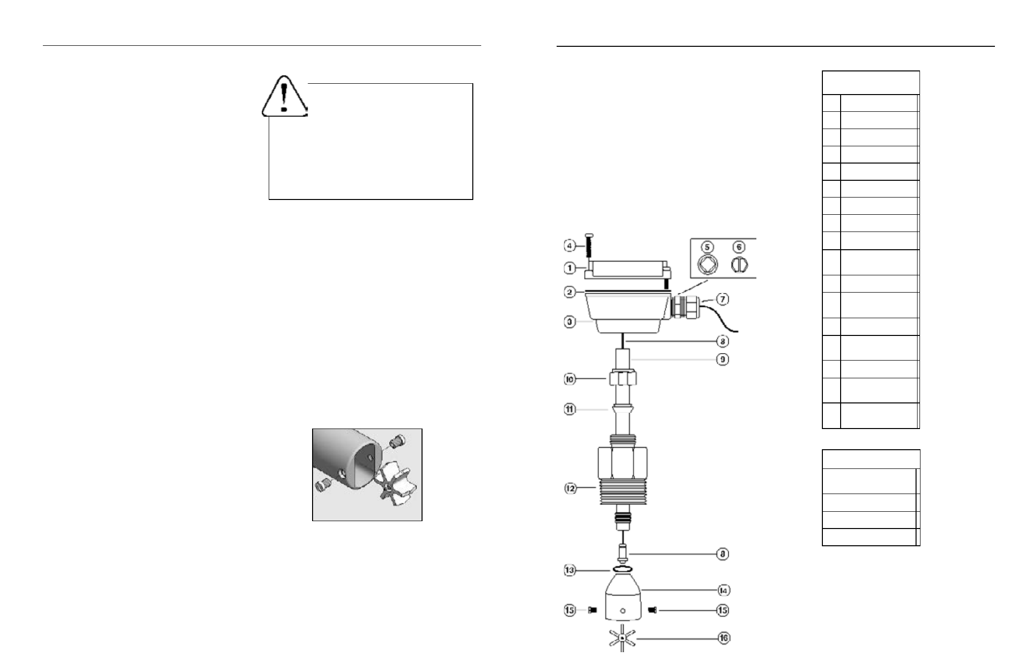
IPFS-0XX Parts
1
Upper housing assembly
2
Gasket
3
Lower housing
4
Housing screw (4 req'd)
5
Plug, steel
6
Plug, plastic
7
Strain relief
8
Pickup, Standard (for RTI)
9
Tube
10
Compression nut
11
Compression ferrule
12
Adapter fitting
13
Rotor housing O-ring (EPDM)
14
Rotor housing
15
Jewel bearings (2 req)
16
Rotor with shaft
17
Rotor repair kit
(includes of #15 & #16)
Page 8
Parts explosion
IPFS-1XX (HOT-TAP) Parts (not shown)
Adapter fitting
Ball valve assembly
Collar, locking
Hex nipple, 2"
Page 9
rotor replacement.
Rotors are easily field-replaced. Shaft
and rotor are a single unit, and are not replaced separately.
If replacement is due only to normal shaft wear, bearing re-
placement is probably not necessary. If the rotor has been
damaged by impact, the bearings should also be replaced.
Rotor and bearings can be ordered as a kit. Follow these
steps:
1. Unscrew the threaded bearing housings to expose
the shaft ends. If bearings are being replaced,
back them completely out.
2. Remove the rotor. Put the new rotor in its place.
3. Thread in one bearing housing part way, then the
other. Take care to start the end of the shaft into
the bearing hole before tightening further.
4. Screw in bearing housings until they bottom.
Note
: Do not use excessive force.
5. Check for free spin. Blowing lightly on the rotor
should result in it spinning rapidly and coasting to
a smooth stop.
rePAir
caution!
Never attempt to remove a flow
sensor when there is pressure in the pipe
unless it is specifically designed for hot
tap installation and removal. Loosen the
compression nut slowly to release any trapped pres-
sure. If fluid sprays out when removing the sensor,
stop turning and depressurize the pipe. Failure to
do so could result in the sensor being thrown from
the pipe, resulting in damage or serious injury.
OPerATiON
Theory.
In principle, an insertion flow sensor measures the
velocity of flow at one point in the pipe, and flow rate and total
can be inferred from this one point. Accuracy is decreased
by any factor which makes the flow at the measured point
unrepresentative of the entire flow stream. This includes
distorted flow patterns caused by upstream fittings too close
to the sensor. The worst offenders are fittings that increase
the flow on one side of the pipe, such as partially-opened
gate or butterfly valves. Fluid moving in a pipe does not all
flow at the same velocity. Toward the center of the pipe,
fluid moves faster than at the wall, and the relationship be-
tween the two changes as overall flow rate increases. This
change in the “velocity profile” can result in non-linearity,
which means that the K-factor that is correct for one flow
rate may be incorrect for another. The recommended depth
settings have been carefully chosen to minimize this source
of error, and should be followed carefully, especially in the
smaller pipe sizes.
Flow range.
These sensors are designed to operate at flow
velocities of 0.3 to 30 feet per second. If erratic readings
are encountered at low flows, check the chart to see if flow
is below minimum for the pipe size. The standard shaft and
bearings should have a long life at continuous high flow.
OPerATiON & rePAir
Refer to "Terms and Conditions of Sale" in our catalog or on
our website. Contact customer service to receive a Returns
Goods Authorization number before shipping your product
back for repair. Be sure to include a brief description of the
problem plus any relevant applciation notes.
WArrANTY/reTUrN