Dwyer IPFS User Manual
Page 2
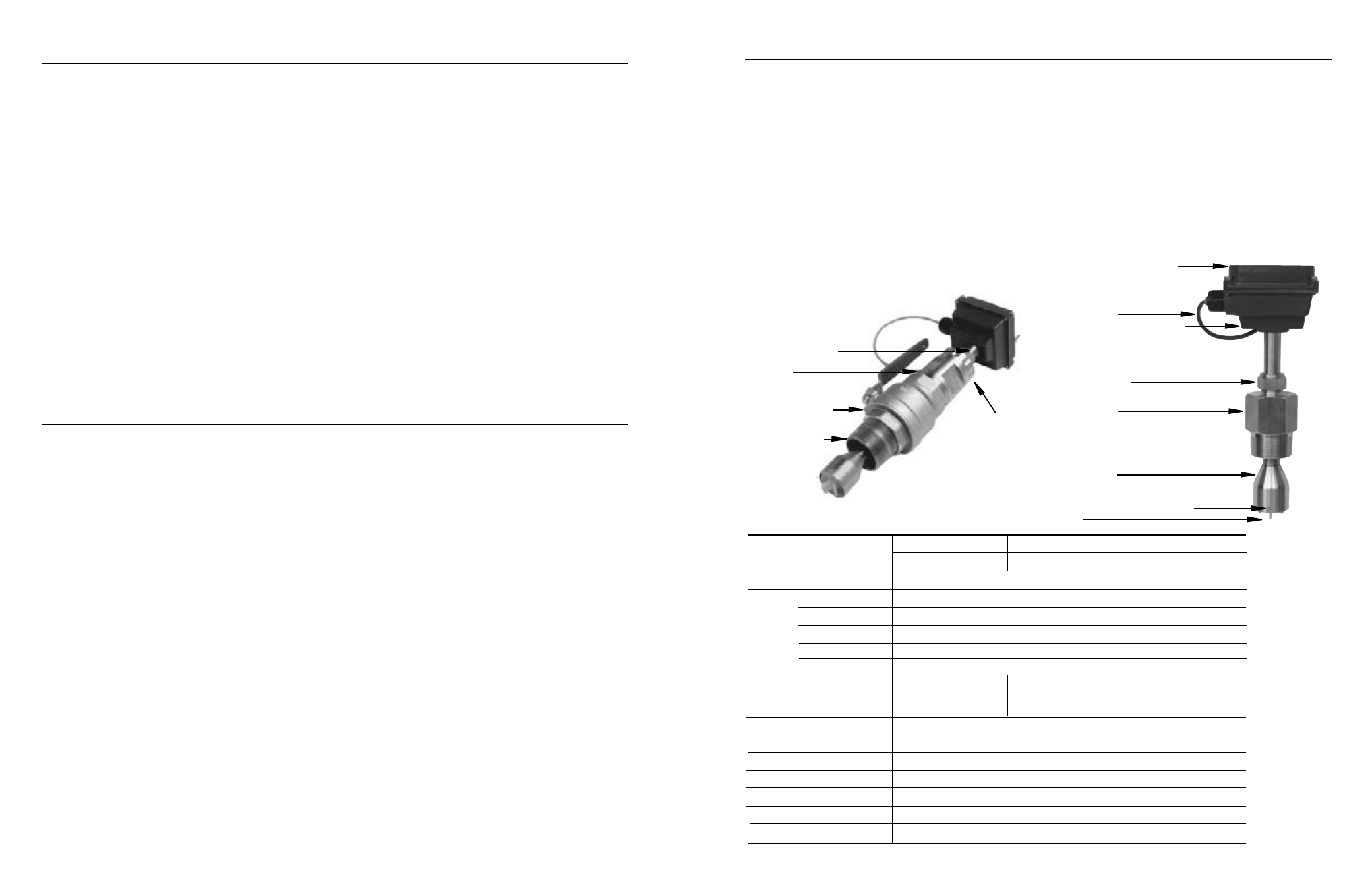
TABLe OF cONTeNTs
General information
General Information, Features, Specifications ................................................................................................. Page 1
installation
Piping, Positioning the Meter, Immersion, Depth Setting ................................................................................ Page 2
IPFS-0 Installation, IPFS-1 Installation ............................................................................................................. Page 3
Dimension C, Pipe Wall Thickness .................................................................................................................... Page 4
Flow Rate ............................................................................................................................................................ Page 4
Straight Pipe Recommendations ...................................................................................................................... Page 5
Full Pipe Recommendations .............................................................................................................................. Page 6
connection
Calibration .......................................................................................................................................................... Page 7
Operation & repair
Theory of Operation, Flow Range, Rotor Replacement .................................................................................... Page 8
repair & Parts
Signal, Parts Explosion, Parts List .................................................................................................................... Page 9
Troubleshooting
Problem, Probable Cause, To Try....................................................................................................................... Back
TABLes AND DiAGrAMs
Features .............................................................................................................................................................. Page 1
Specifications Table ........................................................................................................................................... Page 1
Piping .................................................................................................................................................................. Page 2
Positioning the Meter ......................................................................................................................................... Page 2
Depth Setting ..................................................................................................................................................... Page 2
Meter Installation ............................................................................................................................................... Page 3
Table 1 (Dimension 'C') ...................................................................................................................................... Page 4
Table 2 (Pipe Wall Thickness) ............................................................................................................................ Page 4
Straight Pipe Recommendations ...................................................................................................................... Page 5
Full Pipe Recommendations .............................................................................................................................. Page 6
Connection Diagram .......................................................................................................................................... Page 7
K factor
................................................................................................................................................................ Page 7
Rotor Replacement ............................................................................................................................................ Page 8
Parts Explosion ................................................................................................................................................... Page 9
Parts List ............................................................................................................................................................. Page 9
Troubleshooting: Problem, Probable Cause, To Try .......................................................................................... Back
Page 1
GeNerAL iNFOrMATiON
FeATUres
Adapter fitting with
2” NPT threads
Full-port 2” ball valve
for sensor removal
2” Adapter
removes to mount
hot-tap machine
3/4” diameter tubing
for low insertion force
iPFs-1XX
Rotor
Rugged cast aluminum housing
18 Foot Cable
Modular electronics (optional)
• rate/total/pulse/4-20 mA
• blind 4-20 transmitter
• pulse divider
Compression nut
for easy adjustment, secure locking
Adapter fitting
with 1-1/2” male NPT threads
Rotor housing
Removable jewel bearings for
exceptional low flow performance
iPFs-0XX
sPeciFicATiONs*
GeNerAL iNFOrMATiON
The IPFS Series are adjustable depth insertion paddlewheels
that come in brass or 316 stainless models to fit 3” to 40” pipe.
Installation fittings are standard 1-1/2" or 2” NPT. Fittings such
as saddles and weldolets may be purchased either locally or from
Dwyer Instruments Inc.
Ruby bearings and a non-drag Hall-effect sensor give these meters
the widest flow range of any of the paddlewheel types. A sensor
detects the passage of miniature magnets in the six rotor blades.
The resulting square-wave signal can be sent for hundreds of
feet over unshielded cable without a transmitter and connected
directly to many PLC’s and other controls without any additional
electronics.
If desired, a modular system of electronics can be installed
directly on the flow sensor or mounted remotely. The Series RTI
provides digital rate and total display, as well as programmable
pulse output; the Series RTI also provides a 4 to 20 mA analog
output. The Series BAT is a blind analog transmitter. Program-
mable pulse for pump pacing is available with the Series PWD.
The “hot-tap” models IPFS-1 can be installed or serviced without
shutting down the line by means of a 2” full-port isolation valve
that comes with a nipple for installation on the pipe fitting. In most
circumstances, no special tool is required.
Locking collar
s-size
L-size
3” to 12” (50 - 300mm)
12” to 40” (300 - 1000mm)
Hall Effect sensor, 12 Vdc current sinking pulse
Cast aluminum
Brass or 316 SS
PVDF
Nickel-bound tungsten carbide (zirconia ceramic optional)
Ruby jewel
iPFs-0
iPFs-1
None
Bronze (316SS optional)
1.5” NPT
2” NPT
0.3 - 30 feet/sec (0.1 - 9 meter/sec)
+/- 1.5% of full scale
200˚ F (93˚ C)
200 psi (14 bar)
0.44 x pressure in pipe
5-24 Vdc, 1.5 mA
#22 AWG 3-con, 18’ (6m); 2,000’ (650m) maximum cable run
Pipe size
sensor
Materials Housing
sensor Body
rotor
shaft
Bearings
isolation Valve
Fitting size
Flow range
Accuracy
Maximum Temperature
Maximum Pressure
insertion Force
Power
cable
*Specifications subject to change.