Dwyer IPFS User Manual
Page 3
immersion.
The IPFS Series standard sensors are not designed
for continuous underwater operation. If this is a possibility,
as in a flooded vault, a unit modified for immersion should be
specified (Option -IMM)
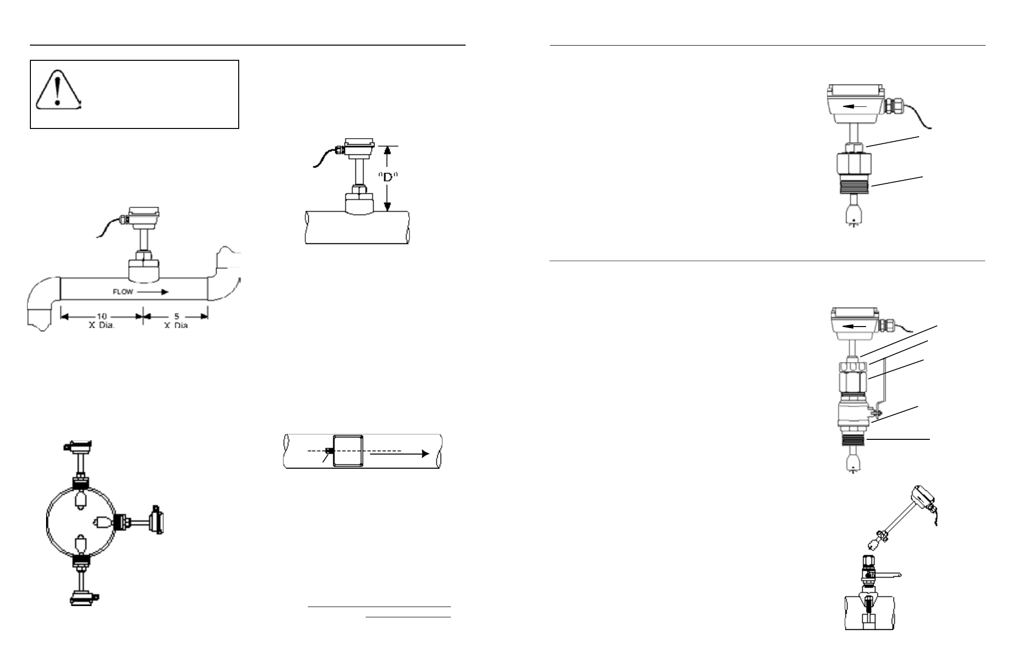
Depth setting.
It is important for accuracy that the sensor be
inserted to the correct depth into the pipe.
1. In Table 1 (on page 4), find Dimension C for your sensor model
and pipe size.
2. Subtract wall thickness of your pipe (Table 2 on page 4) to
find Dimension D.
3. Measuring from the outside of the pipe to the joint in
the housing, as shown in the diagram, adjust the sensor
to Dimension D and hand tighten compression nut.
4. Align the conduit housing with the centerline of the pipe,
as shown below. Be sure the arrow on the housing
points in the direction of flow.
5. Check Dimension D one more time.
6. Tighten the compression nut fully.
recOrD YOUr seTTiNGs
Once you have the meter set up and operational, it is im-
portant to record your meter setttings and save them for
future reference.
K-Factor
Insertion Depth (Dim. D)
iNsTALLATiON
Page 2
POsiTiONiNG THe MeTer
Fair (unacceptable if
air is present)
Fair (unacceptable if fluid
contains sediment)
Best
Piping.
For best results, the IPFS sensor should be installed
with at least ten diameters of straight pipe upstream and five
downstream. Certain extreme situations such as partially-
opened valves are particularly difficult and may require fifteen
diameters upstream. (See Straight Pipe Recommendations.)
Horizontal is the preferred installation orientation, since it
improves low-flow performance slightly and avoids problems
with trapped air. Bottom, top, and vertical pipe installations
are all acceptable if required by the piping layout. (See Full
Pipe Recommendations.)
These flow sensors are not recommended
for installation downstream of the boiler
feedwater pump where installation fault
may expose the meter to boiler pressure
and temperature. Maximum recom-
mended temperature is 200˚ F.
iPFs-0XX iNsTALLATiON
Fitting installation.
IPFS-0XX sensors come with a 1-1/2” male NPT pipe
thread adapter fitting. Any fitting that provides the matching NPT female
thread may be used. Installation procedure compensates for fitting height
differences. Cut a minimum 1-3/4” hole in the pipe. If possible, measure
the wall thickness and write it down for use in depth setting. Then install
the threaded fitting (saddle, weldolet, etc.) on the pipe.
Meter installation.
Loosen the compression nut so that the adapter
slides freely. Pull the meter fully upward and finger-tighten the compres-
sion nut. Using a thread sealant, install the adapter in the pipe fitting. Do
not overtighten. Now loosen the compression nut, lower the meter to the
appropriate depth setting (see diagram and instructions, preceding page).
caution: Do not allow the meter to fall into the pipe uncontrolled, as
this may damag the meter
. Be sure flow is in the direction of the arrow
on the housing. Tighten compression nut fully.
iPFs-1XX iNsTALLATiON
‘Hot tap’ meters are designed to be installed and serviced without
depressurizing the pipe.
Fitting installation.
The hot tap sensors have a 2” NPT thread for
compatibility with the 2” isolation valve. Any fitting that provides matching
NPT female thread may be used. The installation procedure compensates
for differences in fitting height.
If initial installation is performed on an unpressurized pipe, cut a
minimum 1-3/4” hole in the pipe. If possible, measure the wall thickness
and write it down for use in depth setting. Then install the threaded fitting
(saddle, weldolet, etc.) on the pipe.
If it is necessary to do the initial installation under pressure, any standard
hot tap drilling machine with 2” NPT adapter, such as a Transmate or a
Mueller, can be used. Ordinarily, it is not necessary to use an installation
tool, since the small-diameter tube can be controlled by hand but not
for higher pressures.
Meter installation.
Remove the sensor unit from the valve assembly.
Using a thread sealant, install the valve assembly on the pipe fitting. If
the initial installation is a pressure (“hot”) tap, remove the 1-1/2” x 2”
adapter bushing at the back of the valve. Thread the tapping machine on,
open the valve, and tap using a minimum of 1-3/4” or maximum 1-7/8”
cutter. After retracting the machine and closing the valve, reinstall the
flow sensor. When the sensor is secure, open the valve and adjust depth
setting (see diagram and instructions, preceding page). Be sure flow is
in the direction of the arrow on the housing. Tighten locking collar and
compression nut fully.
Compression nut
Adapter fitting
with
standard NPT
threads
Compression nut
2” adapter removes
to mount hot-tap
machine
Full-port 2” ball
valve allows sensor
removal
Standard 2”
NPT threads
iPFs-1XX sensor
removal
Locking collar
iNsTALLATiON
Page 3
FLOW
strain relief