Dwyer GFM User Manual
Page 7
3
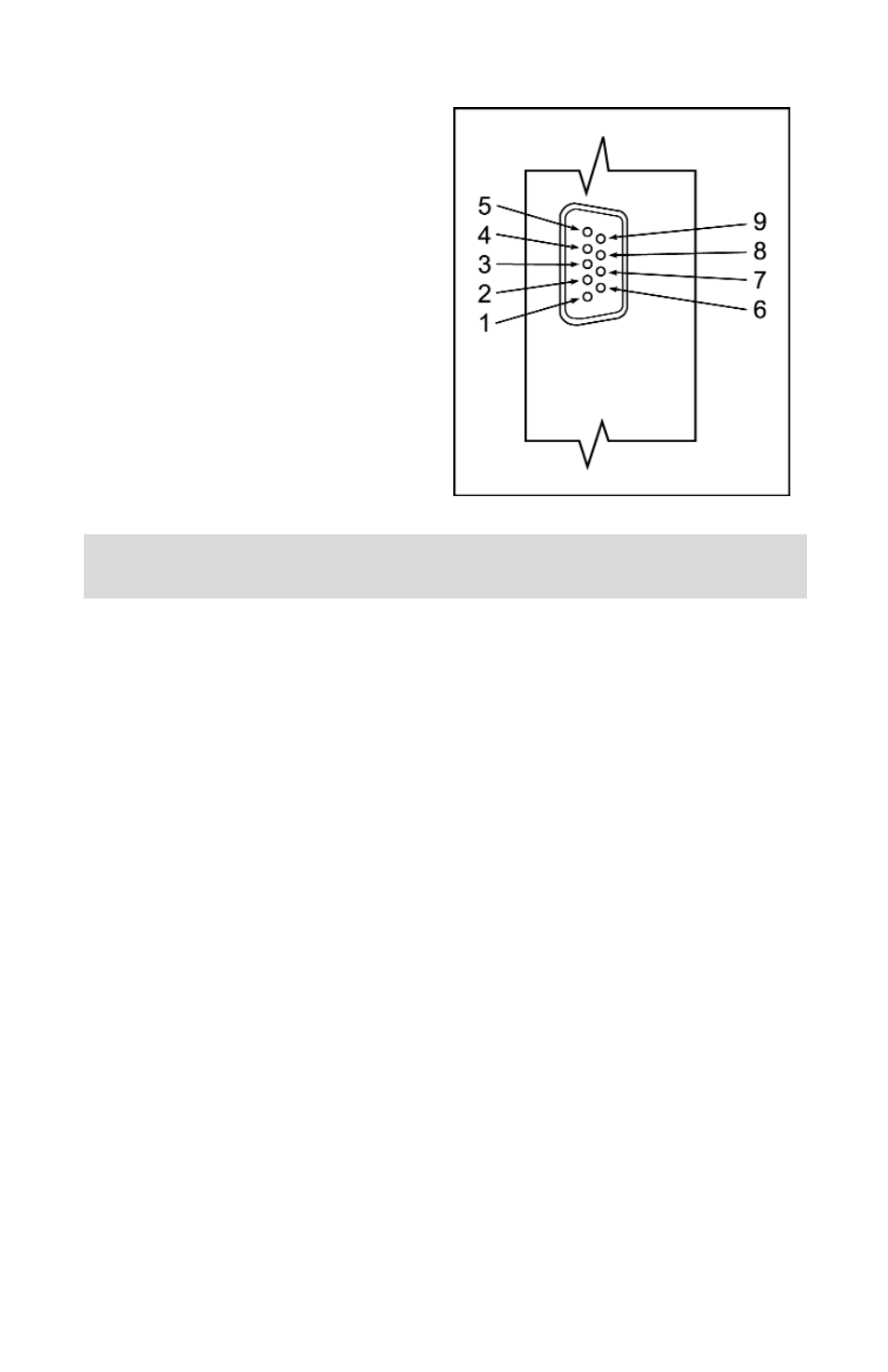
PIN
FUNCTION
1
Remote LCD display signal
2
0 to 5 VDC output indication
3
0 to 5 VDC common
4
Power supply, positive
5
Power supply, common
6
Remote LCD display reference
7
(unassigned)
8
4 to 20 mA output indication
9
4 to 20 mA common
FIGURE 2.a - 9-PIN “D” CONNECTOR PINOUTS FOR GFM TRANSDUCER.
IMPORTANT NOTES:
In general, “D” Connector numbering patterns are standardized. There are, how-
ever, some connectors with nonconforming patterns and the numbering sequence
on your mating connector may or may not coincide with the numbering sequence
shown in our pin configuration table above. It is imperative that you match the
appropriate wires in accordance with the correct sequence regardless of the par-
ticular numbers displayed on your mating connector.
Make sure power is OFF when connecting or disconnecting any cables in the system.
When connecting power to the GFM mass flow meter via the DC power jack, do
not connect any power supply to the 9-pin 'D' Connector. The DC power jack has
a center positive polarity.
When battery use is required to power the GFM, use only the optional battery and
accompanying charger available from Dwyer.
The power input is protected by a 750mA M (medium time-lag) resettable fuse. If
a shorting condition or polarity reversal occurs, the fuse will cut power to the flow
transducer circuit. Disconnect the power to the unit, remove the faulty condition,
and reconnect the power. The fuse will reset once the faulty condition has been
removed.
Cable length may not exceed 9.5 feet (3 meters).
Use of the GFM flow transducer in a manner other than that specified in this man-
ual or in writing from Dwyer, may impair the protection provided by the equipment.
ƽ