Dwyer GFM User Manual
Page 16
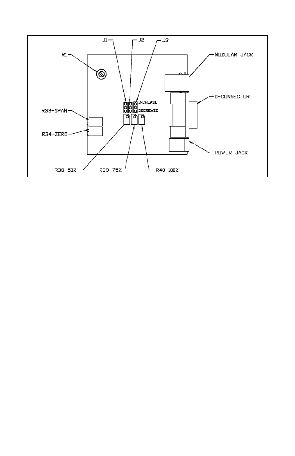
FIGURE 7.A - CALIBRATION POTENTIOMETER AND JUMPER LOCATIONS
7.2
Calibration of GFM Mass Flow Meters
All adjustments in this section are made from the outside of the meter, there is no
need to disassemble any part of the instrument.
GFM Mass Flow Meters may be field recalibrated /checked for the same range
they were originally factory calibrated for. When linearity adjustment is needed, or
flow range changes are being made proceed to step 7.3. Flow range changes
may require a different Restrictor Flow Element (RFE). Consult your distributor or
Dwyer for more information.
7.2.1
Connections and Initial Warm Up
At the 9-pin “D” connector of the GFM transducer, connect the multimeter to out-
put pins [2] and [3] for 0-5 VDC (or pins [8] and [9] for 4-20 mA)-(see Figure 2.a).
Power up the Mass Flow Meter for at least 30 minutes prior to commencing the
calibration procedure.
7.2.2
ZERO Adjustment
Shut off the flow of gas into the Mass Flow Meter. To ensure that no seepage or leak
occurs into the meter, it is good practice to temporarily disconnect the gas source.
Using the multimeter and the insulated screwdriver, adjust the ZERO potentiometer
[R34] through the access window for 0 VDC (or 4 mA respectively) at zero flow.
12