Maintenance – Blue Angel Pumps 63042-BLA1 User Manual
Page 4
4
Operating Instructions
2 HP Grinder Pumps
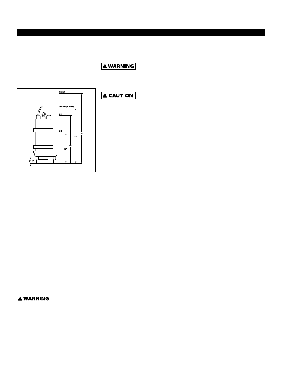
Note: If pump is not mounted on a
lift-out rail system, the leg kit needs
to be installed. Set leg height so a 3”
– 4” clearance is achieved between the
bottom pump inlet and basin bottom.
Maintenance
Only qualified mechanics with proper
tools and knowledge should attempt to
service this pump.
REPlAcING GRINDER IMPEllER AND
sHREDDING RING
Note: This is the only disassembly
operation permitted in the field. All
other repairs must be performed at an
authorized service center or the factory.
standard Tools Required:
• Standard socket wrench set
• Standard set of open-end
wrenches
• Hammer
• Vise grip pliers
• Allen head socket set
• Screwdrivers
• Wire brush
Disconnect all power
and control wires to
motor at the control panel before starting
the disassembly operations. Do not rely
upon opening the circuit breaker only.
Hazardous cutter.
Rotation of the cutter
with hands in the cutter area can cause
loss of fingers. Keep hands away from
the pump inlet opening when working
on or handling the pump for any reason.
Pump should be
sanitized with bleach
before starting work.
• Pump should be thoroughly
cleaned of trash and deposits
before starting disassembly
operations.
• Wear protective gloves and
clothing.
• Always use a rag on the impeller
when turning to prevent cutting
hands on the sharp edges of the
shredding ring.
DIsAssEMbly oF sHREDDING RING
AND GRINDER IMPEllER
1. Remove 3 bolts from grinder ring
flange with socket wrench. The
grinder ring is pressed into the
flange for convenient removal.
2. Thread 2 of the bolts (removed from
the grinder ring flange) into the
tapped back-off holes in the flange
and evenly tighten the bolts to back
the grinding ring out of the pump
housing.
3. Hold the grinder impeller by prying
against the impeller cutting bar and
remove the cap screw from the end
of the shaft.
4. Use a large screwdriver to the slot
of the shaft and tap on the cutter
vane with a hammer. Tap in a
counterclockwise direction (thread is
right-hand).
5. If the impeller removes easily, clean
and replace if worn.
6. Make sure the pump impeller has
not loosened when the grinder
impeller was removed. This can be
checked on reassembly of grinder
impeller and shredding ring. The
tips of the impeller cutter vanes
should extend 1/8” below the
bottom of the shredding ring. If
the distance is greater, the pump
impeller has loosened. If the
distance is less, shredding ring is not
properly seated.
7. After the volute case has been
removed, wrap emery cloth around
the shaft and hold with vise grip
pliers. Us a cloth on the impeller and
thread tight against shoulder on
shaft.
8. Clean all threads with a wire
brush and file smooth any nicked
threads. Apply an anti-seize or other
graphite compound on threads
before replacing grinder impeller.
9. Make sure cap screw in bottom of
pump shaft is tight. Hold impeller
with screwdriver between the cutter
bar and teeth of shredding ring
while tightening the cap screw.
10. Make sure the impeller turns freely
by hand after reassembly. Some
drag will be present due to the
shaft seals. There should not be any
binding or tight spots when turning
the grinder impeller.
11. If there is any rub or drag on the
shredding ring, loosen the 3 bolts
in the shredding ring plate and
tap lightly with the hammer to
loosen. Retighten the bolts. Be
sure to tighten the bolts evenly,
applying pressure on all 3 bolts. DO
NOT COMPLETELY TIGHTEN ONE
BOLT BEFORE TIGHTENING THE
OTHER BOLTS. THIS WILL CAUSE
MISALIGNMENT AND LOCKING OF
SHREDDING RING AND GRINDER
IMPELLER.
HP
Voltage
Phase
breaker size
Heater size
2
230
3
20 Amp
K-50
2
460
3
15 Amp
K-33
chart 3
www.waynewatersystems.com
Figure 3 - leg Kit