Control panel and level sensing, 2 hp grinder pumps, 3operating instructions – Blue Angel Pumps 63042-BLA1 User Manual
Page 3: Chart 2
3
Operating Instructions
2 HP Grinder Pumps
The double seal grinder pumps contain
an electrode for detecting water within
the unit. The electrode is housed within
the seal chamber, isolated from the
motor chamber by a mechanical shaft
seal. If the electrode detects water
within the oil-filled housing, it will close
the circuit to the alarm light in the
control panel, indicating the motor must
be serviced before the upper mechanical
shaft seal fails. The BLUE conductor is
connected to the seal leak probe.
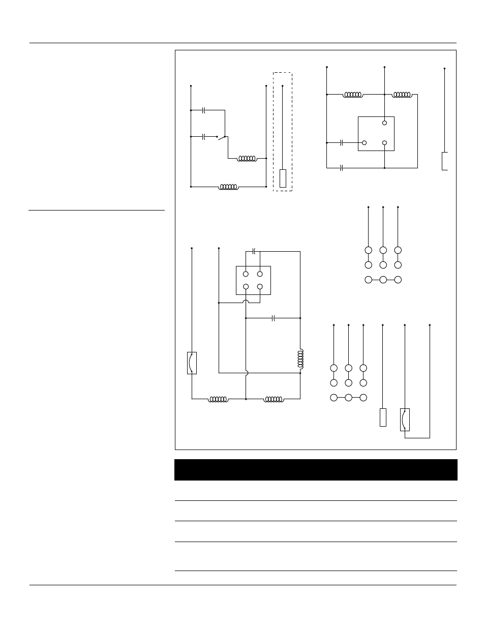
Refer to Wiring Diagrams for model
specific wiring directions (See Figure 2).
control Panel and
level sensing
BAGP1 & BADSGP1 grinder pumps
have internal start and run capacitors.
No control panel is required for
operating the pump. An alarm box is
recommended for high water alarm.
See Chart 2 for starting component
specifications per model.
BARDSGP1 and BAHGP2 models require
control boxes containing properly sized
start and run capacitors. Single-phase
models require a Single-Phase Control
Box with starting components equal to
specifications listed in Chart 2.
The three-phase models require a Three-
Phase Control Box with circuit breaker
and overload heaters per the chart.
Intrinsically safe type float controls are
recommended for all applications. An
intrinsically safe control panel relay will
limit the current and voltage to the level
controls. A control panel can be supplied
with this type of circuitry.
Recommended level sensing settings:
1. The lower “turn-off” control should
be set so the pump stops with the
liquid level at the top of the motor
housing.
2. The upper “turn-on” control should
be set approximately 8” above the
“turn-off” control. This should limit
the number of pump starts to not
exceed 10 starts per hour.
3. The “lag-on” control for duplex
operation should be set 4” above
the “turn-on” control.
4. The “alarm” control is set 10” above
the “turn-on” control.
5. No control should be set above the
inlet pipe.
Start Windings
Main Windings
Run Cap.
Start Cap.
Cent Switch
1.
WHITE
2.
BL
A
CK
3.
RED
BAGP1
BADSGP1
1
2
3
7
8
9
4
5
6
1.
WHITE
2.
BL
A
CK
3.
RED
BL
UE
M
oistur
e S
ensor
Ther
mal S
ensor
WHITE
BR
O
WN
230 Volt 3 Phase
60Hz
BARDSGP1-2023
1.
WHITE
2.
BL
A
CK
Start Windings
Main Windings
5
2
1
3.
RED
Run Cap.
Start Cap.
4.
BL
UE
M
oistur
e S
ensor
BARDSGP1-2021
230 VAC, 1 Phase 60 Hz
Start Relay
Main Windings
Main Windings
Star
t W
indings
4
1
3
2
Start Cap.
Run Cap.
Ther
mal S
ensor
1.
WHITE
2.
BL
A
CK
4.
LEAD
3.
RED
230 Volt 1 Phase
60Hz
BAHGP2-2021
230 Volt 3 Phase
60Hz
4
5
7
1
8
2
1.
WHITE
2.
BL
A
CK
6
9
3
3.
RED
BAHGP2-2023
4.
BL
UE
M
oistur
e S
ensor
BADSGP1
(only)
Figure 2 - Wiring Diagram
www.waynewatersystems.com
Model #
start
capacitor
Run
capacitor
starting
Relay
BAGP1-115
BADSGP1-115
200mF
250 Vac
70mF
250 Vac
NA
BAGP1-2021
BADSGP1-2001
270-300mF
250-370 Vac
30mF
300 Vac
NA
BARDSGP1-2021
270-300mF
250-370 Vac
30mF
300 Vac
GE
3ARR3J3G3
BAHGP2-2021
BAHGP2-2021C
BAHCP2-2021E1
400mF
250 Vac
90mF
250 Vac
Stearns
477104012401
chart 2