Cb a – Badger Meter Vortex Meters User Manual
Page 25
Form No. 09-VRX-UM-00007
23
The simple appearance of the flow meter may tempt an installer to handle it as an ordinary nipple. Re-
member, it is a precision electronic instrument. Treat it with care.
1) To install a flare fitting, first remove any burrs from the pipe ends, then slide the flare nut onto the
pipe. Push it back far enough so that it will be out of the way when you use the flaring tool.
2) Clip the pipe in the flaring tool, keeping the end flush with the face of the tool.
3) Slowly turn the handle on the tool until it bottoms out.
4) Unscrew the handle and remove the tool to check the quality of the flare. (If the flare isn’t smooth
or even the first time, cut off the end with your pipe cutter, and try the technique again.)
5) Line up and tighten the nut and flared pipe to the fitting body. Make the connection as tight but
not so tight as to distort the flow meter body.
Always use two wrenches when turning a fitting onto the flow meter, one across the flats on the flow
meter end, close to the fitting, and one on the fitting.
Do not use tools inside the flow meter, as this may damage the vortex sensor, and invalidate the war-
ranty.
The flow meter may be mounted in any orientation.
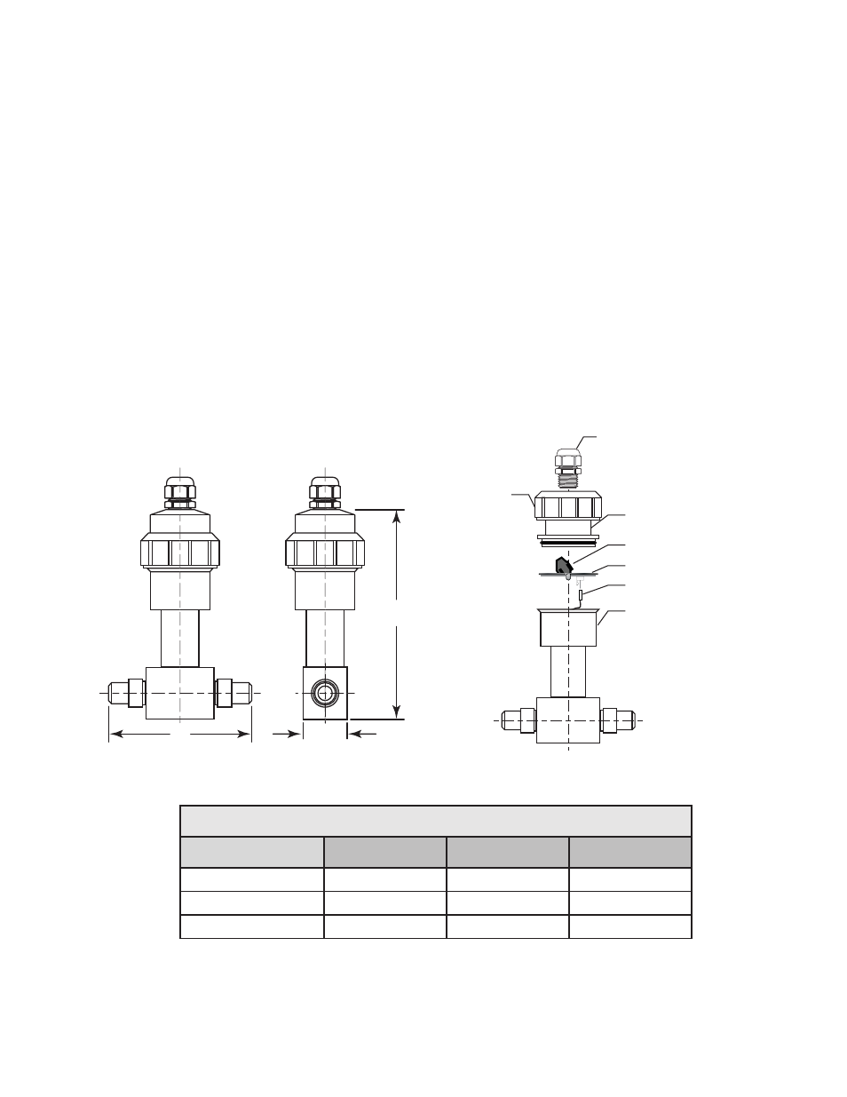
C
B
A
TERMINAL STRIP
ELECTRONICS MODULE
THREE PIN CONNECTOR
FLOW SENSOR BODY
COVER
CONDUIT ADAPTOR
CORD GRIP
FIGURE 16
RVL (Tube) Dimensions
Tube Size (inches)
A
B)
C
½
1.31 (33.3)
6.25 (158.8)
4.87 (123.7)
¾
1.31 (33.3)
6.25 (158.8)
4.66 (118.4)
1
1.44 (36.6)
6.59 (167.4)
5.42 (137.7)