Rvl (tube) series, Mechanical installation – Badger Meter Vortex Meters User Manual
Page 24
22
Form No. 09-VRX-UM-00007
RVL (TUBE) SERIES
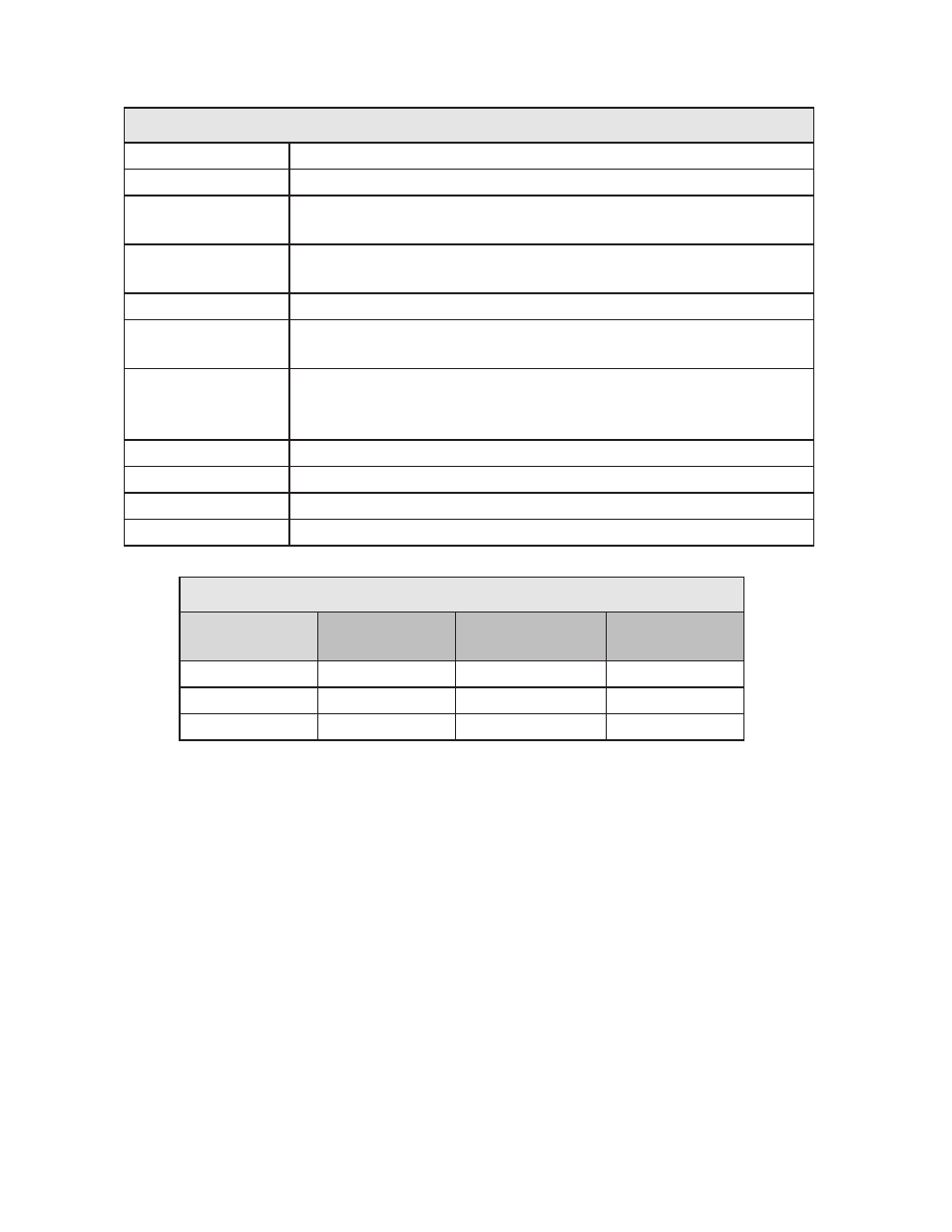
RVL (Tube) Specifications
Fluid:
Liquids
Connection:
Tube (Flare end)
Turndown Ratio:
12:1 (¾”, 1”)
8:1 (½”)
Accuracy:
±1% of full scale (4-20 mA or 0-5 VDC)
±2% of full scale, frequency pulse
Repeatability:
±0.25% of actual flow
Materials
PVC standard
CPVC, Polypropylene, PVDF optional
Output Signals:
4-20 mA standard
0-5 VDC or frequency pulse optional (Push - Pull Driver) 150 mA
Sink or Source
Power Supply:
8 to 28 VDC
CSA Certification:
CSA File 215035, CSA Standard C22.2 No. O-M and No 142-M
Response Time
2 seconds minimum, step change in flow.
Enclosure:
Type 4X (IP 66)
RVL (Tube) Nominal Flow Rates
Tube Size
(inches)
Minimum Flow
gpm (lpm)
Maximum Flow
gpm (lpm)
Weight
lbs (Kg)
½
0.6 (2.3)
5 (18.9)
1.5 (0.68)
¾
1.3 (4.7)
15 (56.8)
1.6 (0.72)
1
2.1 (7.9)
25 (94.6)
1.7 (0.77)
MECHANICAL INSTALLATION
This meter will provide years of accurate service if good flow meter installation practices are followed.
The flow meter should be installed where pipe vibration is minimal.
Observe the upstream piping requirements listed under “Piping requirements”. Upstream valves should
not be used to control flow rate. They should always be kept fully open. Good quality ball valves with
integral unions may be connected directly to the flow meter if the valves are fully open during operation.
This allows easy isolation and removal of the flow meter, should maintenance be required. Cavitation
and flow rate pulsation will adversely affect flow meter performance.
Diaphragm or piston pumps may not be used. Do not use Teflon tape or any kind of pipe dope when pip-
ing.