Operate in the shaded region, Figure 9 – Badger Meter Vortex Meters User Manual
Page 12
10
Form No. 09-VRX-UM-00007
100
200
300
400
500
600
700
800
900
1000
1100
10
12
8
14
16
18
20
22
24
26
28
Supply Voltage (VDC)
Loop Load (Ohm's)
Operate in the
Shaded Region
Supply Voltage - 8 VDC
0.02
= Maximum Loop Resistance
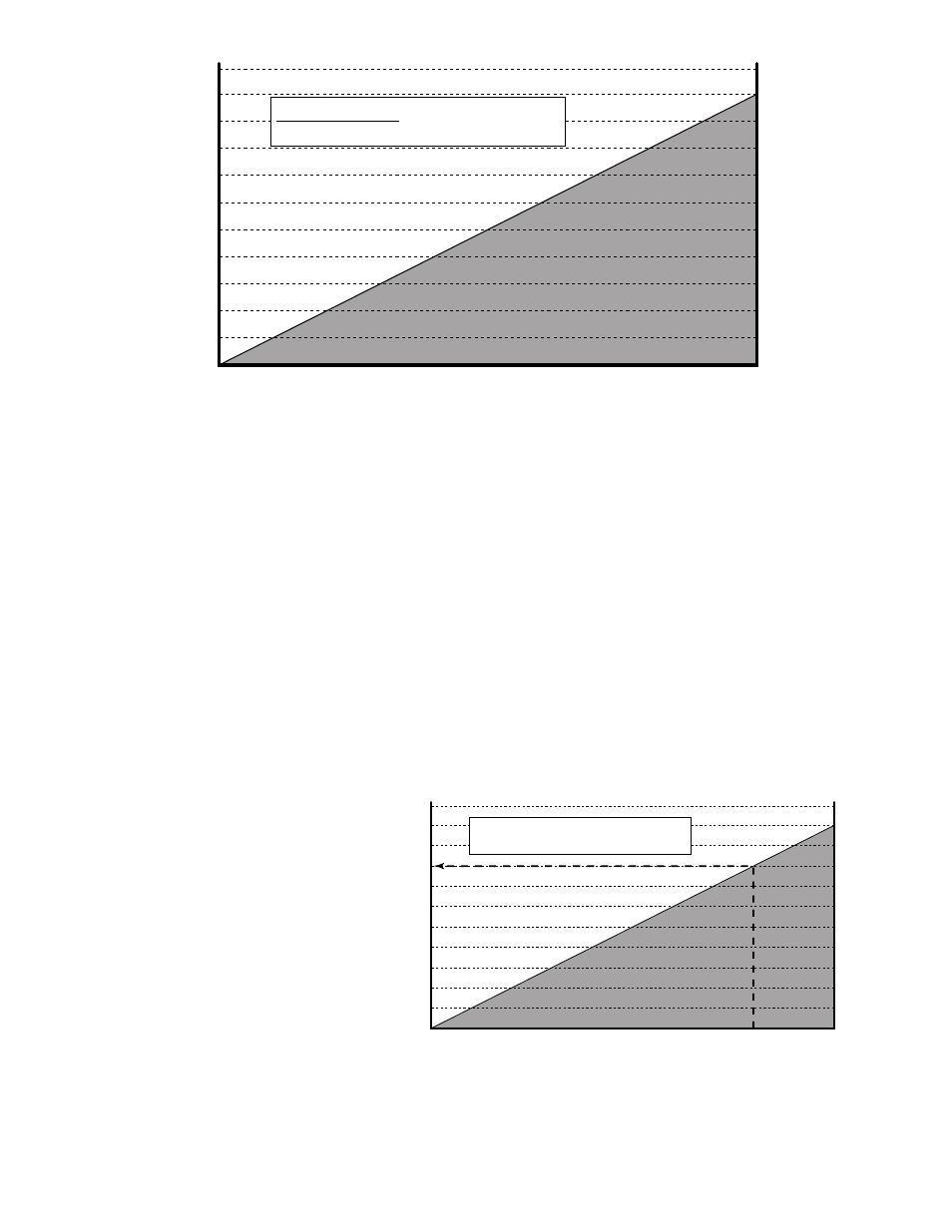
FIGURE 8
To use this figure, first add the resistance of all the receivers, indicators, etc., and the wire in the loop.
If the wire resistance is unknown, use a value of 50 Ohm for a twisted wire of 1,000 feet or less with a
gauge of #22 AWG or heavier.
Find the total load (in ohms) on the left hand side of the chart in figure 8 and follow that value horizon-
tally until it intersect with the shaded area.
From the intersection point look straight down to where a vertical line would intersect the voltage scale.
This is the minimum voltage needed for the transmitter to operate properly under the specific load con-
ditions.
Example: After checking the specification for all the loads in an application the total amounted to
800 ohms. Following the 800 ohm line in figure 9 to the right the intersection point is about ¾ of the
way across the chart in figure 9.
A vertical line through the intersec-
tion point crosses the voltage axis at
about 24 VDC so with a load of 800
ohms a standard 24 volt power sup-
ply would be used.
100
200
300
400
500
600
700
800
900
1000
1100
10
12
8
14
16
18
20
22
24
26
28
Supply Voltage (VDC)
Loop Load (Ohm's)
Operate in the
Shaded Region
Supply Voltage - 8 VDC
0.02
= Maximum Loop Resistance
FIGURE 9