Descrizione dei componenti, Circuito frigorifero, Caratteristiche dell'acqua – Airedale EcoChill 6kW - 46kW User Manual
Page 9: Struttura e ventilatori, Circuito idraulico standard, Description of components, Refrigerant circuit, Water characteristics, Structure and fans, Standard hydraulic circuit
9
EcoChill Installation Manual 7481930_v1.6.0_08_2013
ECL-ECLH 020-202
EN
5.
DESCRIPTION OF COMPONENTS
5.1. REFRIGERANT CIRCUIT
SCROLL COMPRESSORS
High efficiency rotary scroll hermetic compressor
(mounted on elastic anti-vibration mounts) with two
pole electric motor. Crankcase heaters as standard,
automatically activated when the unit stops, as long as
power is maintained to the unit.
SYSTEM SIDE HEAT EXCHANGER
Brazed plate heat exchanger in stainless steel AISI 316.
The heat exchanger is externally insulated with closed
cell neoprene anti-condensation material.
DESUPERHEATER
(Only version "D")
Brazed plate heat exchanger in stainless steel AISI 316.
The heat exchanger is externally insulated with closed
cell neoprene anti-condensation material.
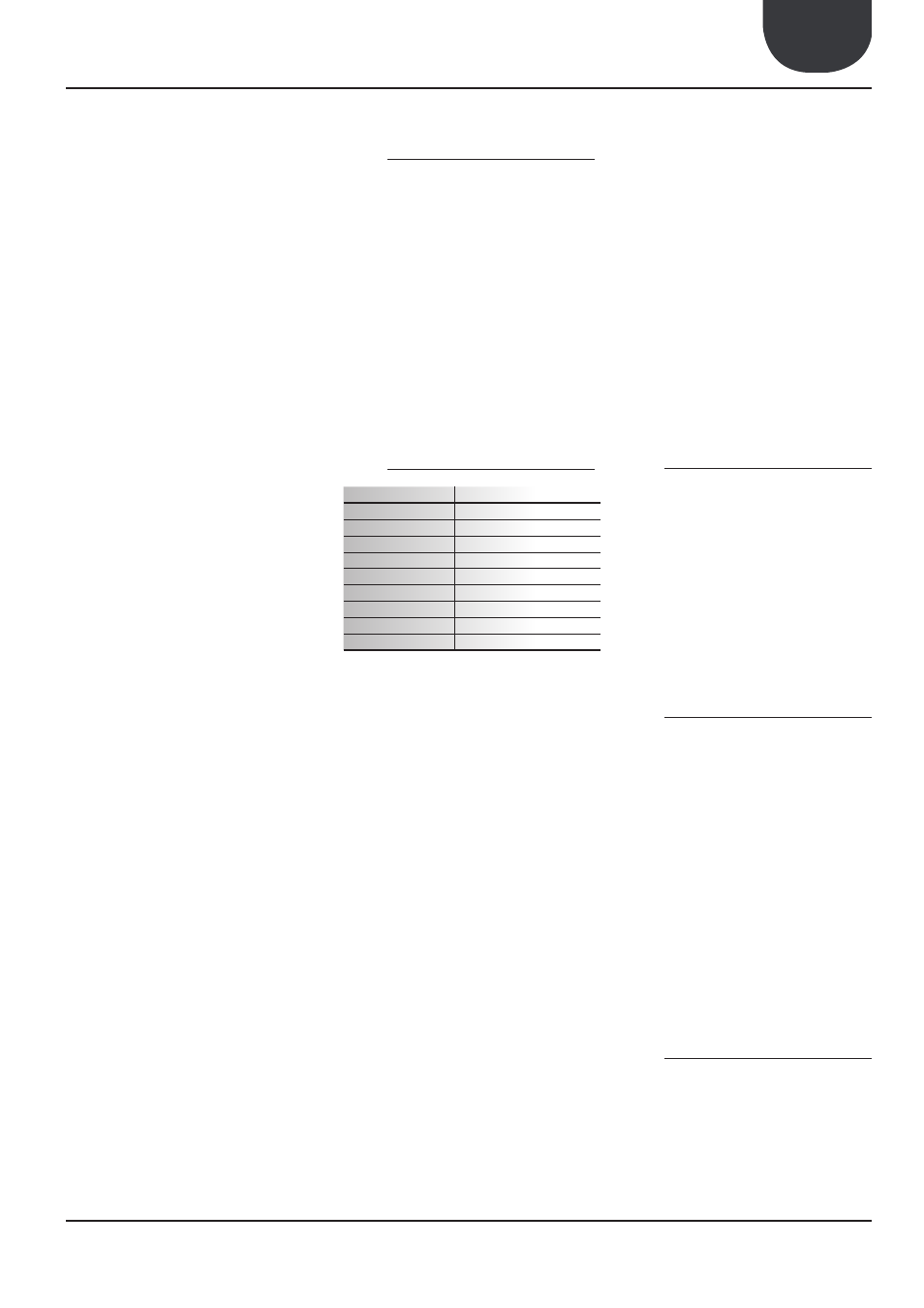
5.2. WATER CHARACTERISTICS
PH
6-8
Electrical conductivity Less than 200 mV/cm (25°C)
Chloride ions
Less than 50 ppm
Sulphuric acid ions
Less than 50 ppm
Total iron
Less than 0.3 ppm
Alkalinity M
Less than 50 ppm
Total hardness
Less than 50 ppm
Sulphur ions
None
Ammonia ions
None
Silicone ions
Less than 30 ppm
SOURCE SIDE MICROCHANNEL HEAT EXCHANGER
(ECL 102 ÷ 202 COOLING ONLY)
All aluminium finned coil heat exchanger of microchan-
nel type. Ensures:
1. Higher energy efficiency that standard coils.
2. Lower refrigerant charge.
SOURCE SIDE STANDARD HEAT EXCHANGER
(ECL 020 ÷ 090 COOLING ONLY)
(ECL 020 ÷ 202 HEAT PUMP)
Finned coil heat exchanger with copper tubes and
aluminium fins adequately spaced to ensure high
efficiencies.
REVERSING VALVE
(only versions "H")
4 way reversing valve. Reverses the flow of refrigerant.
LIQUID ACCUMULATOR
(only versions "H")
Compensates for the difference in volume between the
finned coil and the plpate heat exchanger, retaining the
excessive liquid.
FILTER DRIER
Hermetic type with ceramic cartridge and hygroscopic
material, capable of retaining impurities and moisture
within the refrigerant circuit.
CHECK VALVE
Allows the flow of refrigerant in one direction only.
THERMOSTATIC EXPANSION VALVE
Mechanical type, with external equaliser located at the
evaporator outlet, modulates the flow of refrigerant
into the evaporator based on the load and ensures the
correct superheat of the suction gas.
HOT GAS INJECTION VALVE
(only version "D")
Hot gas injection device upstream of the evaporator.
LIQUID SIGHT GLASS WITH MOISTURE INDICATOR
Used to check for the presence of moisture in the
refrigerant circuit.
LIQUID AND DISCHARGE ISOLATING VALVES
(version "C)
Permit the isolation of refrigerant in case of special
maintenance.
5.3. STRUCTURE AND FANS
STRUCTURE
The main structure is made from hot dip galvanised
steel panels, polyester powder coated and designed
to ensure the maximum access for service and main-
tenance.
The base for sizes 102 - 152 - 202 heat pump units has
holes in the proximity of the coil to permit drainage
of water during the defrost cycle.
FAN ASSEMBLY
External rotor axial fan with helicoidal blades, housed
in a casing, complete with protective grilles. 6 pole
electric motor with thermal protection.
5.4. STANDARD HYDRAULIC CIRCUIT
WATER FILTER
The water filter is provided with a filter mesh with
holes no greater than one millimetre, blocking and
removing from the unit any impurities found in the
hydraulic circuit.
FLOW SWITCH
(on ECL 025…040°A|HA)
The flow switch monitors the flow rate through the
heat exchanger and stops the unit in case of insuf-
ficient flow.
DIFFERENTIAL PRESSURE SWITCH
(on ECL 020…202° -°P N|H - HP N)
(on ECL 050…202°A Q |HA Q)
Located between the inlet and outlet of the evapora-
tor. Monitors the flow rate through the heat exchanger
and stops the unit in case of insufficient flow.
5.4.1. ADDITIONAL COMPONENTS DETAILED IN
THE CONFIGURATOR
PUMPS
Standard or high head
EXPANSION TANK
Membrane type precharged with nitrogen.