Advanced Protection XGA User Manual
Page 9
9
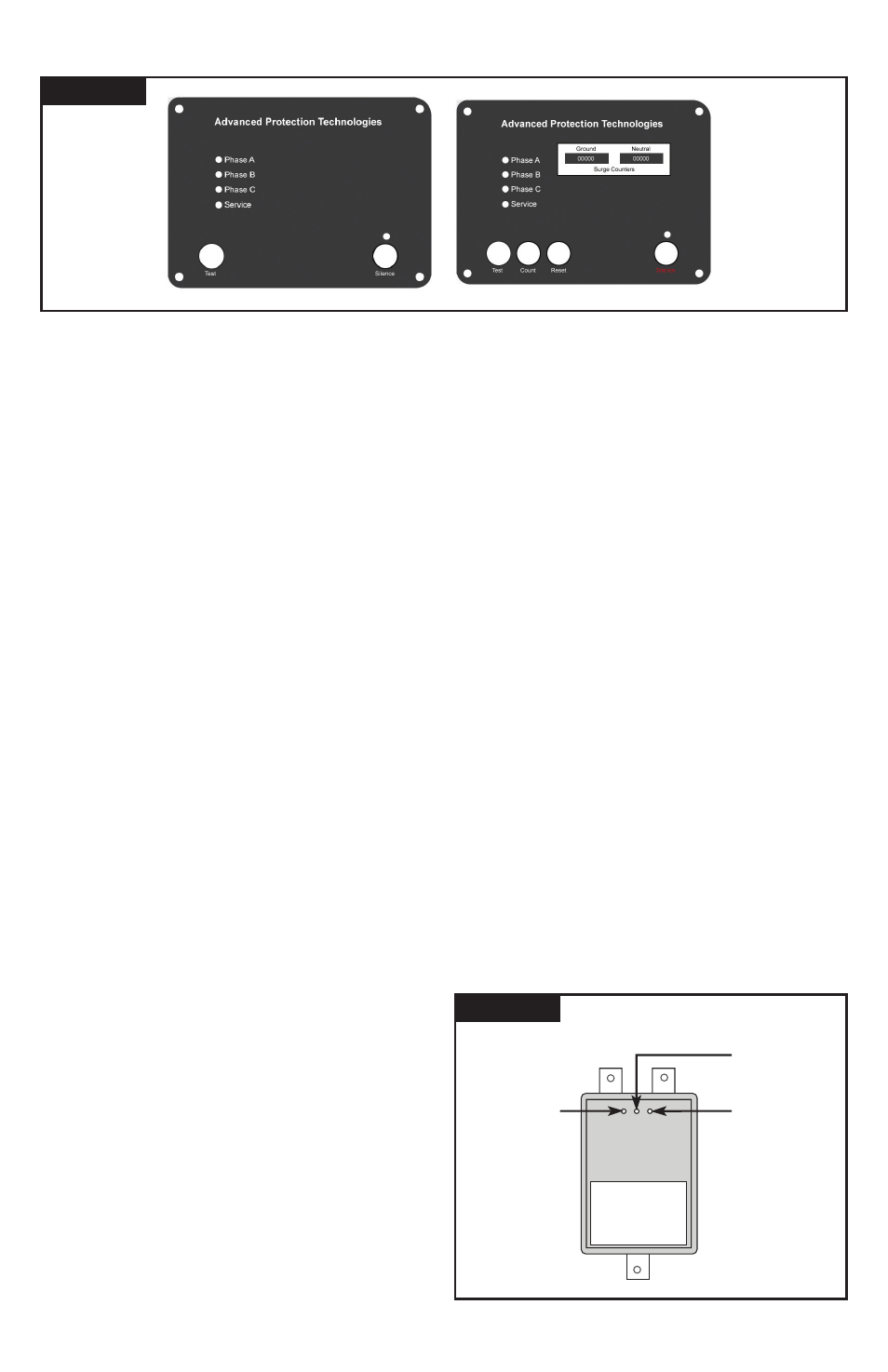
Figure 14
Figure 15
XGA
Control and
Diagnostics
Panel With
Dual Surge
Counter
Option
XGA
Control and
Diagnostics
Panel
Control and Diagnostic Panel
All indicators and controls are located on the front diagnostic
panel. Green LEDs indicate correct operation.
Phase A, B & C: Tri-Color LED status indicators – one per phase
Green – Full Protection
Amber – Partial Protection
Red – No Protection
Service LED (red): LED illuminates in the event of problem.
This indicator is logic-connected to the Phase LEDs. Should a
Phase LED go out, the red Service LED will illuminate and the
Audible Alarm will sound.
Test: Tests red Service LED and Audible Alarm regardless
of Alarm Silence status; does not cycle optional dry contacts
Alarm Silence: Turns Audible Alarm off (Audible Alarm is
deactivated when LED is illuminated)
Surge Counter Count: (if equipped) Increments optional surge
counter by one (+1)
Surge Counter Reset: (if equipped) Resets optional surge
counter to zero (0)
If an inoperative condition where to occur, the built-in audible
alarm will sound and the red Service LED will illuminate. This
indicates that the unit needs evaluation by a qualified electrician
or technician. Until a qualified person evaluates the unit, press
Alarm Silence to silence the alarm. (The LED above Alarm
Silence illuminates when the alarm is deactivated. Normal
operation occurs with the Alarm Silence LED extinguished.)
The red Service LED will remain illuminated even though the
Audible Alarm has been silenced. Test tests the red.
Service LED and the Audible Alarm
Diagnostics will indicate a failure upon loss of voltage or
significant drop in voltage. Be aware that ground faults
on ungrounded or resistive ground systems will trigger a
failure alarm on this SPD.
If LEDs are illuminated in a manner that suggests
contradictory information, there may be an internal logic
problem and the unit needs replaced. If none of the LEDs
are illuminated, the unit may not be installed correctly. For
troubleshooting assistance, please contact APT Technical
Support at (800) 237-4567.
Surge Counter Options
The surge counter registers the number of transient
overvoltages on all L-N and L-G modes since the counter
was last reset. The counter is inductively coupled from each
mode of protection. It increments upon significant current
change in a short time period (large di/dt).
The surge counter includes Test and Reset buttons on
the touchpad display. Pressing Test adds one count.
Pressing Reset clears the counter’s memory and sets the
display to zero.
The counter option includes a SuperCap internal storage
capacitor that provides backup power for up to four
days in the event of a power outage. This eliminates the
maintenance of battery backups. There is a 10-15 minute
charging cycle before the counter(s) operate.
Single Counter – Totals the surges through the L-N and L-G
Dual Counters – Is used to distinguish between L-N and
L-G surges. Two separate counters are used, with common
Reset and Test tabs.
Supplemental LED indicators on Modules
Each module includes three LEDs per Figure 15. The
center green LED indicates power is on. This green LED
should be illuminated during normal operation.
When the upper left red LED is illuminated, the module’s
L-G protection is lost.
When the upper right red LED is illuminated, the module’s
L-N protection is lost.
MODULE LEDs
Green
LED lit:
power on
Red
LED lit:
loss of surge
suppression
from line to
neutral
Red
LED lit:
loss of surge
suppression
from line to
ground