Table 1: model number decoder – Advanced Protection XGA User Manual
Page 5
5
raceway connections. Do not use isolating bushings to interrupt
a metallic raceway run.
A separate isolated ground for the SPD is NOT recommended.
Proper equipment connections to grounding system and
ground grid continuity should be verified via inspections and
testing on a regular basis as part of a comprehensive electrical
maintenance program.
On 4-Wire Power Systems, neutral to ground bonding (Main
Bonding Jumper) must be installed per the NEC
®
. Failure to
do so WILL damage SPDs.
UL 1283 required language concerning the installation
of EMI Filters
a) An insulated grounding conductor that is identical in
size and insulation material and thickness to the grounded
and ungrounded circuit supply conductors, except that
it is green with or without one or more yellow stripes,
is to be installed as part of the circuit that supplies the
filter. Reference should be made to Table 250-122 of the
National Electrical Code regarding the appropriate size of
the grounding conductor.
fail SPDs. For this reason, the NEC
®
Article 285 has placed
SPD restrictions on ungrounded systems. As generalizations,
SPDs for ungrounded systems can be installed on grounded
systems with a clamping performance penalty. However, SPDs
for grounded systems installed on ungrounded systems are
almost certainly destined for premature failure. Call APT Tech
Support at (800) 237-4567 for further information.
System Grounding
An equipment grounding conductor must be used on all
electrical circuits connected to the SPD.
For the best performance, use a single point ground system
where the service entrance grounding electrode system is
connected to and bonded to all other available electrodes,
building steel, metal water pipes, driven rods, etc. (for reference
see: IEEE Std 142-2007).
For sensitive electronics and computer systems, we
recommend that the ground impedance measurement be
as low as possible. When metallic raceway is used as an
additional grounding conductor, an insulated grounding
conductor should be run inside the raceway and sized per the
NEC
®
. Adequate electrical continuity must be maintained at all
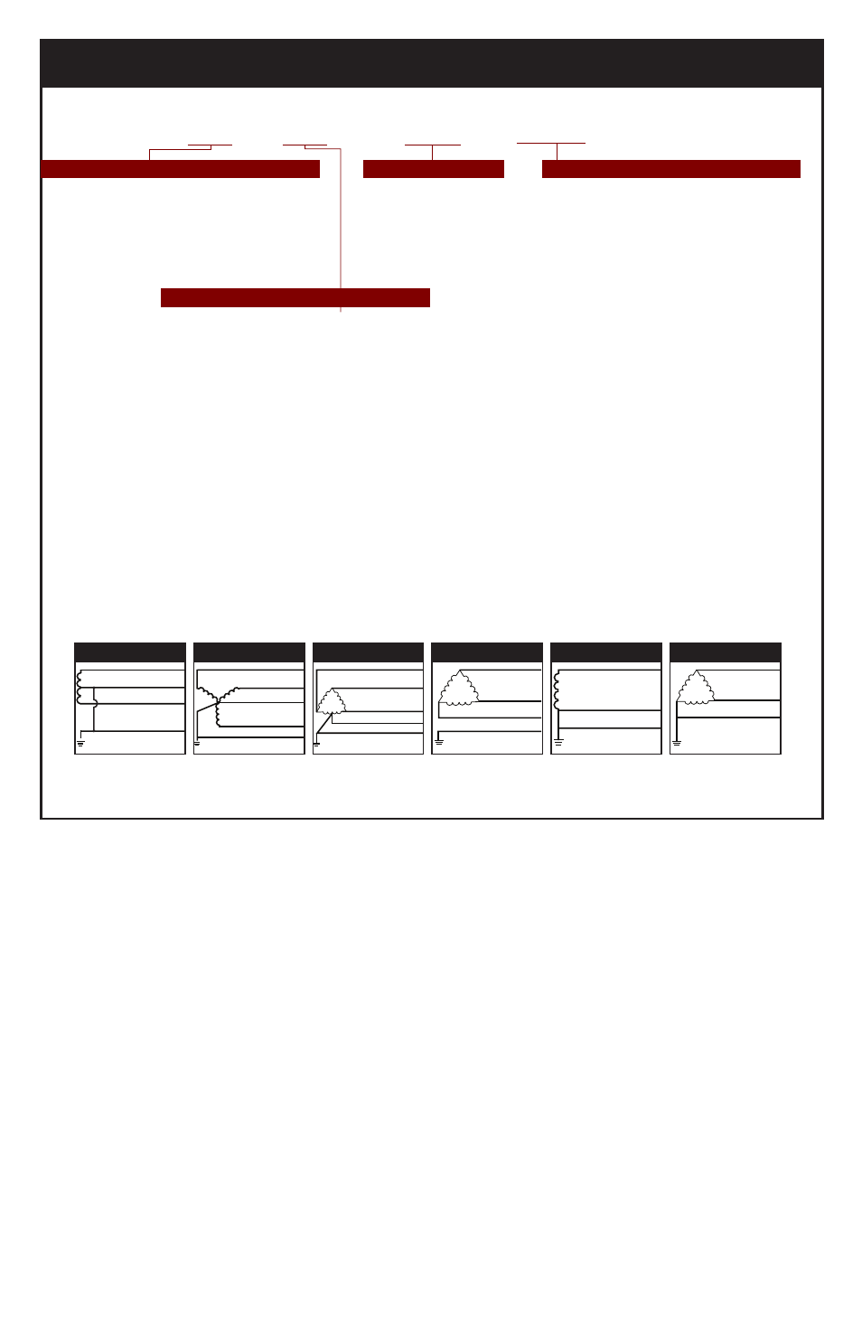
Table 1: MODEL NUMBER DECODER
Do not create model numbers from this chart as all features are not available on all models
Figure 1
Figure 2
Figure 3
Figure 4
Figure 5
Figure 6
SPLIT
2 Hots, 1 Neu, 1 Grnd
HI-LEG DELTA (B High)
3 Hots, (B HIGH),
1 Neu, 1 Grnd
SINGLE POLE
1 Hot, 1 Neu, 1 Grnd
WYE
3 Hots, 1 Neu, 1 Grnd
DELTA & HRG WYE
3 Hots, 1 Grnd
CORNER GROUND
DELTA (B grounded)
2 Hots, 1 Grnd
Hot (BLK)
Hot (BLK)
Neutral (WHT)
V
V
}
}
Ground (GRN)
}
Phase A (BLK)
Phase B (BLK)
Neutral (WHT)
Phase C (BLK)
Ground (GRN)
A
C
N
V
B
Phase A (BLK)
Phase B (ORNG)
Neutral (WHT)
Phase C (BLK)
Ground (GRN)
}
V
V
}
Neutral (WHT)
Hot (BLK)
Ground (GRN)
Phase A (BLK)
Phase C (BLK)
Phase B (BLK)
Ground (GRN)
}
V
Phase A (BLK)
Phase C (BLK)
Ground (GRN)
V
}
TE = Transient Eliminator, Listed Type 2
SPD in NEMA 1 enclosure
XTE = Transient Eliminator, Recognized
Type 4 SPD on backplane for installation
within gear in Type 2 installation (display
on 6’ cable)
Common North American Systems:
1 = 240/120V Split Phase - 1Ø 3W+Grnd (Fig 1)
2 = 208Y/120V Wye - 3Ø 4W+Grnd (Fig 2)
3 = 240/120V High Leg Delta (B High) (Fig 3)
4 = 480Y/277V Wye - 3Ø 4W+Grnd (Fig 2)
5 = 480V Delta - 3Ø 3W+Grnd (Fig 4) & HRG Wye
8 = 600Y/347V Wye - 3Ø 4W+Grnd (Fig 2)
Other Available Systems - Confirmation encouraged:
15 = 254/127V Split Phase - 1Ø 3W+Grnd (Fig 1)
18 = 480/240V Split Phase, or Two legs of Wye (Call)
21 = 220Y/127V Wye - 3Ø 4W+Grnd (Fig 2)
41 = 520Y/300V Wye - 3Ø 4W+Grnd (Fig 2)
42 = 415Y/240V Wye - 3Ø 4W+Grnd (Fig 2)
43 = 400Y/230V Wye - 3Ø 4W+Grnd (Fig 2)
44 = 440Y/250V Wye - 3Ø 4W+Grnd (Fig 2)
51 = 480V B Corner Grnd Delta, 3Ø 3W+Grnd (Fig 6)
06 = 240V Delta - 3Ø 3W+Grnd (Fig 4)
61 = 240V B Corner Grnd Delta, 3Ø 3W+Grnd (Fig 6)
07 = 380Y/220V Wye - 3Ø 4W+Grnd (Fig 2)
09 = 600V Delta - 3Ø 3W+Grnd (Fig 4) & HRG Wye
91 = 600V B Corner Grnd Delta, 3Ø 3W+Grnd (Fig 6)
/240
/090
/130
/170
/DC
/SC
/2S
/12
/3R
/04
/FM
/4X
/4S
/TN
RM
Available Accessory (order seperately)
(Note: Enclosure-less version for OEM uses XTE prefix)
=
=
=
=
=
=
=
=
=
=
=
=
=
=
=
240kA Option
090kA SAD option
(120/240V & 208Y/120)
130kA SAD option
(120/240V & 208Y/120)
170kA SAD option
(120/240V & 208Y/120)
Dry Contacts
Two sets Form C (24V, 1A)
Surge Counter, six digit LCD
Dual Surge Counter
NEMA 12 Enclosure (12” x 12” x 6”)
NEMA 3R Enclosure
(12” x 12” x 6” - display inside door)
NEMA 4 Enclosure
(12” x 12” x 6” - display inside door)
Flush Mount enclosure, NEMA 1 only
(wall cavity size: 12”x12”x6” deep)
NEMA 4X Non-metallic enclosure
(polycabonate, 14”x12”x6” - display inside door)
NEMA 4S Stainless Steel enclosure
(12”x12”x6” - display inside door)
NEMA 1/12/3R/4 Enclosure
(10” x 10” x 6”)
Remote Monitor
XGA = XGA Family
160kA rating standard
Model Family
Voltage Code for Electrical System
Option Suffixes (Seperated by slashes / )
ll
/
ll
/
XGA /
lll
/
lll
...