Advanced Protection XGA User Manual
Page 2
2
INTRODUCTION
Thank you for choosing an APT Surge Protective Device
(SPD). This is a high quality, high energy surge suppressor
designed to protect sensitive equipment from damaging
transient overvoltages.
Proper installation is important to maximize performance.
Please follow steps outlined herein.
This entire Operation & Maintenance Manual should be
read prior to beginning installation. These instructions are
not intended to replace national or local codes. Follow
all applicable electrical codes to ensure compliance.
Installation of this SPD should only be performed by
qualified electrical personnel.
APT SPDs are extensively tested in accordance with industry
standards such as ANSI/IEEE C62.41.1, C62.41.2, C62.45,
C62.62, C62.72, UL 1449, UL 1283, IEC 61643, etc.
This SPD is a single-port parallel-connected device
intended for service entrance, panelboard or downstream
installation for IEEE Category C, B or A applications.
Major Industry Nomenclature Changes
Effective 2008-2009
Be aware that UL 1449 Third Edition and 2008 NEC
®
Article
285 generated substantial changes.
▪
The term TVSS changed to SPD
▪
Types 1, 2, 3 & 4 SPDs are created
▪
UL 1449 clamping voltage performance testing
changed from 500A to 3,000A
▪
UL 1449 added new I nominal testing (I
n
), which
consists of more rigorous duty-cycle testing
This SPD complies with the latest regulatory actions and
is UL Listed as such.
For further information, please review latest editions of
NEC
®
Art. 285, UL 1449 or contact APT Tech Support at
(800) 237-4567.
GENERAL INFORMATION
This is a Type 2 SPD. It includes internal overcurrent protection.
Type 2 SPDs are suitable for installation on the load side of the
service disconnect overcurrent device.
This device features internal overcurrent and overtemperature
protection that will disconnect effected surge suppression
components at the end of their useful life, but will maintain
power to the load – now unprotected. If this situation is
undesirable for the application, follow these instructions for
servicing or replacing the device.
Service of this unit consists of replacing internal modules and/
or display assembly.
There are no user-serviceable parts inside the replaceable
modules. Do not attempt to disassemble the module as it stores
charge and is potted.
Simplified Explanation of Operation
SPDs sense overvoltage and create a momentary short
circuit to redirect harmful surge energy to earth ground.
Then they reset automatically and wait for the next surge.
This is similar to the pressure relief valve on a water
heater: pressure goes up, valve opens to relieve pressure
and then resets. In an electrical system, an SPD senses
overvoltage, shorts temporarily sending energy to ground
and then resets. SPDs are capable of repeating this
function thousands of times.
Parallel Connection
This is a Parallel connected SPD – not series connected.
As outlined above, an SPD ‘drains off’ excessive voltage
from an electrical system. Because of parallel connection,
installation of the SPD near the equipment to be protected
is satisfactory. This effect is similar to flushing any toilet in a
house; pressure in the shower goes down. In an electrical
system, a parallel connected SPD will remove excessive
voltage off the entire system (assuming reasonable
proximity).
Tip: It is critically important that wiring leads be configured as
short & straight as possible. Avoid long leads. Avoid sharp
bends. Route SPD conductors in the same conduit. Leads do
not have to be sized for the entire load – this SPD is parallel
connected, not series connected. As a generalization, 6 AWG
works fine.
Precautionary Statement Regarding SPDs on
Ungrounded Systems
Caution – Ungrounded systems are inherently unstable and
can produce excessively high line-to-ground voltages during
certain fault conditions. During these fault conditions, any
electrical equipment including an SPD, may be subjected
to voltages which exceed their designed ratings. This
information is being provided to the user so that an informed
decision can be made before installing any electrical
equipment on an ungrounded power system.
Unpacking & Preliminary Inspection
Inspect the entire shipping container for damage or signs
of mishandling. Remove the packing materials and further
inspect the unit for any obvious shipping damages.
If any damage was found and is a result of shipping or
handling, immediately file a claim with the shipping company
and forward a copy to APT.
Storage Environment
This SPD should be stored in a clean, dry environment.
Storage temperature range is -40°C (-40°F) to +60°C
(+140°F). Avoid exposure to high condensation.
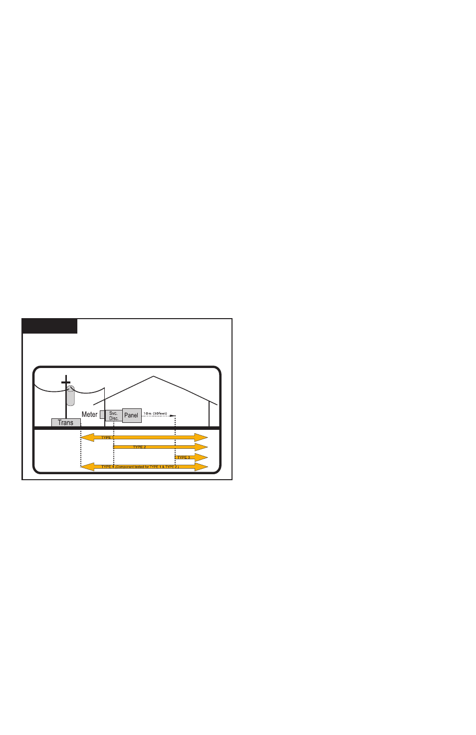
SPD Types: Types 1, 2, 3, & 4
Based on Location within electrical distribution system
(also coincides with ANSI/IEEE C62.41.2 - 2002 Categories C, B & A)
Figure 1
NEC
®
Article 285 & UL 1449-3