Figure 17 troubleshooting flowchart – Advanced Protection XGA User Manual
Page 11
11
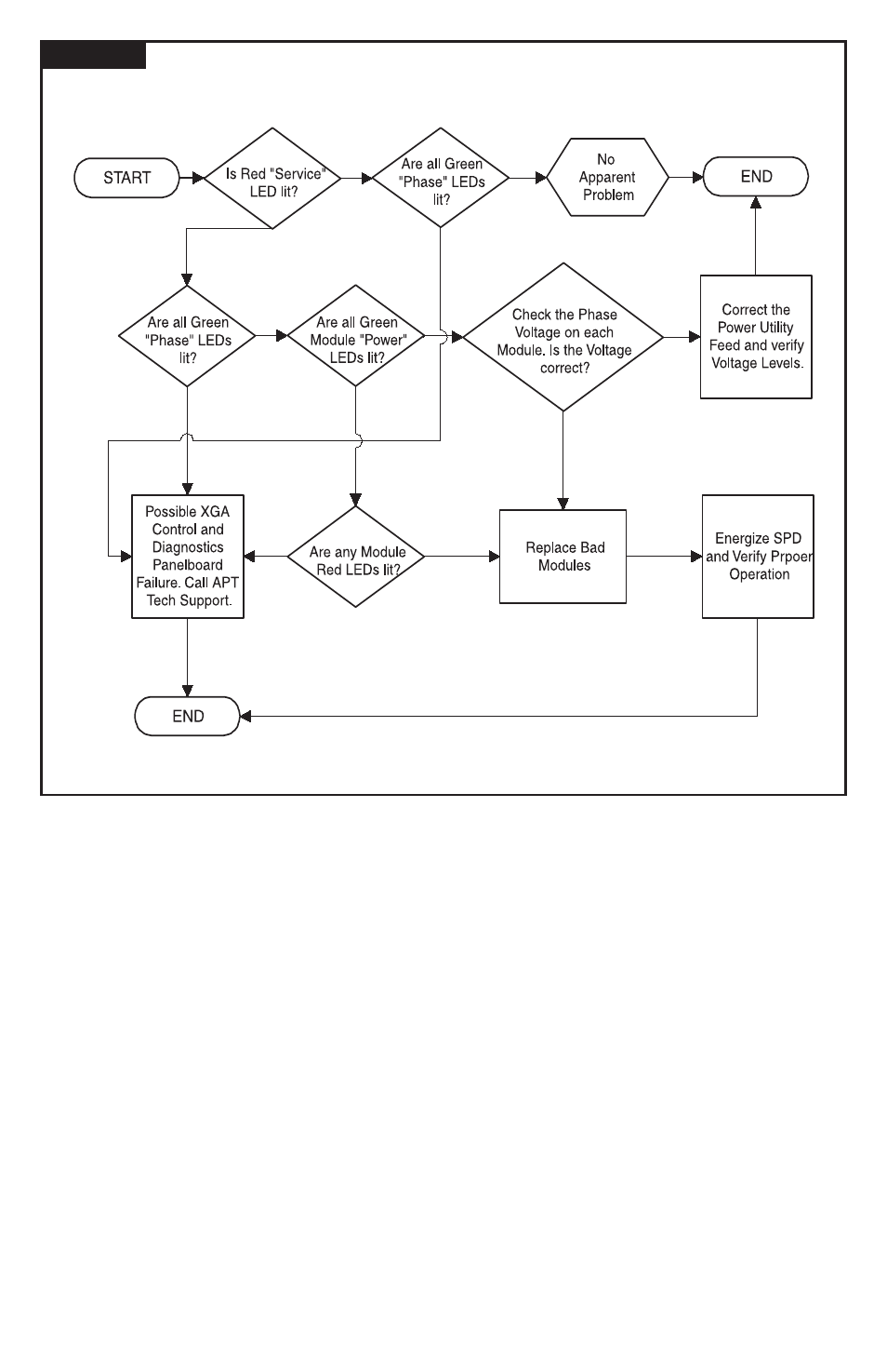
Figure 17
TROUBLESHOOTING FLOWCHART
No
Yes
No
No
Yes
No
Yes
Yes
No
No
No
Yes
Yes
Module Removal and Replacement
Disconnect power to the SPD. DISCHARGE INTERNAL
CAPACITORS BY GROUNDING. Unplug the 10 pin
connector from the XGA module. Using a 7/16” socket
wrench, remove the bolts on both ends of the module, and
pull the module out. Make note of the location and part
number of each module removed, as this part number is not
referenced anywhere else on the SPD. The module(s) should
only be replaced with a new module bearing the same part
number as the module(s) previously removed. Replace with
a new module by reversing the procedure. Torque bolts to 65
inch-pounds, power up the SPD and verify the green module
LED is lit and all alarms have been cleared.
Display/Diagnostic Board Removal and Replacement
Disconnect power to the SPD. Remove the nuts from
the switches that secure the board to the panel, then
remove the board. Remove the connectors one at a
time from the existing board and insert them into the
appropriate connector on the replacement board. Install
the replacement board into the panel and install the nuts
onto the switches and tighten securely.
Note that a sealing gasket between the display and the
enclosure is a key component ensuring weather resistance.
Replace the gasket whenever the display is removed.
Preventive Maintenance (Inspection and Cleaning)
Inspection of the SPD should be performed periodically
to maintain reliable system performance and continued
transient voltage surge protection. While it is difficult to
establish a preventive maintenance schedule because
conditions vary from location to location, inspections for
inoperative modules and other signs of trouble utilizing
the built-in diagnostics should be performed on a routine
basis (weekly or monthly).
Corrective Maintenance (Repair)
APT’s Surge Protective Devices are designed for years
of reliable, trouble-free operation. Unfortunately, even
the most reliable equipment can become inoperative.
On-line diagnostics are an integral part of the SPD and
will aid in isolating which of the protection module(s) have
become inoperative. To keep the SPD operating at peak
performance, replacement of any inoperative module(s)
should be performed according to module removal and
replacement instructions at the earliest service opportunity.
Troubleshooting procedures should be used to isolate
other problems not associated with inoperative module(s).
See Figure 17, Troubleshooting Flow Chart on page 10 for
assistance. Be sure to replace components with identically
rated parts to continue proper operation and safety. Table
3 lists typical replacement parts.