Advanced Protection XGA User Manual
Page 4
4
The XGA is approximately 5.25 in. (133 mm) deep. The XGA
will not flush mount unless there is at least 5.25 in. (133 mm)
of clearance. The XGA is not designed to flush mount on a
typical 2 x 4 stud wall.
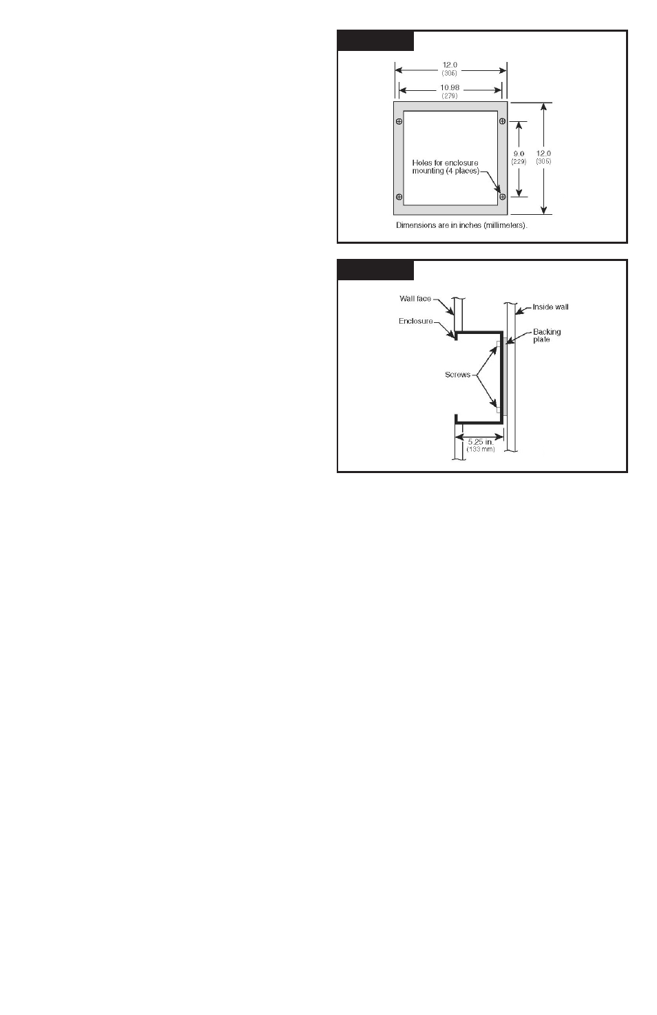
Follow steps 1-5 to flush mount the XGA.
1. Before removing the trim, disconnect the ribbon cables
and ground wire from the modules.
2. Mount the device as close as possible to the panel being
protected. Create a wall opening slightly larger than 12
in. high by 12 in. wide (305 mm high by 305 mm wide).
See figure 2.
3. Install a backing plate inside the wall cavity 5.25 in.
(133 mm) from the wall face such that the XGA will be
supported from its back. See figure 3. Note the mounting
holes on the back of the enclosure. Also note that the
XGA weighs 25 lb (12 kg) maximum.
4. Configure the electrical conductor and conduit
connections consistent with the wiring instructions
beginning on page 7.
5. Carefully reattach the ribbon cables and the ground wire
to the modules and reattach the display panel/cover
before energizing and testing the device.
Terminals
Terminals will accept 14 - 2 AWG conductor and are provided
for line (phase), neutral (if used), and equipment safety
ground connections. 8 AWG is the minimum recommended
wire size because UL testing and evaluation was performed
using 8 AWG.ators to ensure proper operation. We also
recommend keeping the SPD clean as appropriate.
Shortest Leads Possible
• Leads must be as short and straight as possible-
See NEC
®
Art. 285.12
• Pretend wire is $1000 per foot coming out of your pocket
• No long leads
• No sharp bends
• No wire nuts
• How short is short enough? As short as you can make it
• How long is too long? If anyone else can make it shorter
Configuration Management & Part Numbering System
TE series correct installation orientation is such that the door
will hinge from the left. (XTE has no enclosure or door and is
typically factory installed)
Locate the unit’s printed identification nameplate on the inside
of the hinged door, although options may dictate placing it in
a conspicuous location elsewhere. The model number can
be decoded as follows:
• TE identifies an external mount Transient Eliminator
®
followed by a slash (/). XTE identifies an enclosure - less
model followed by a slash (/).
• A one or two digit number will precede the letters XGA.
This number indicates the voltage and wiring configuration
of the device. Refer to page 5 to identify and confirm
correct application.
• XGA identifies the XGA Series, followed by a slash (/)
• Following the second slash may be a /240. These numbers
identify optional per phase Surge Current Ratings. (Please note:
The Standard 160kA Rating does not have a /160 identifier.)
Options are identified after the Surge Current Rating and
are individually separated by a slash. (Options are detailed
later in this manual.)
Example: TE/2XGA/240/DC/RM/4X identifies a Transient
Eliminator
®
XGA Series SPD (external mount), 208Y/120V, 3
Phase, 4 Wire (plus Ground), with a 240kA per phase Surge
Current Rating with: Dry Contact, Remote Monitor and a
NEMA 4X Enclosure.
Voltage Rating
Before installing SPD, verify that it has the same voltage
rating as the power distribution system. Compare the SPD’s
nameplate voltage or model number and ensure that SPD
configuration matches the intended power source. See Table 1.
The specifier or the user of the device should be familiar with the
configuration and arrangement of the power distribution system
in which any SPD is to be installed. The system configuration
of any power distribution system is based strictly on how the
secondary windings of the transformer supplying the service
entrance main or load are configured. This includes whether
or not the transformer windings are referenced to earth via a
grounding conductor. The system configuration is not based on
how any specific load or equipment is connected to a particular
power distribution system.
480V System Example: SPDs should be installed per the
electrical system, not per a load or motor’s wiring connection.
For example, a 480V three phase motor might appear to be
connected as a 480V Delta. In actuality, the serving distribution
system might be a 480Y/277V grounded Wye, with or without
a neutral pulled to the motor or MCC. The system is still a
480Y/277V Wye, even though the load is connected as a
Delta. A grounded Wye has a defined reference to ground
(i.e., neutral is bonded to ground). Some Delta systems are
ungrounded, which have no reference to ground and are known
to become unstable in certain situations. Such instability can
cause line to ground voltage fluctuations that may prematurely
Figure 2
FLUSH MOUNT FRONT VIEW
Figure 3
FLUSH MOUNT SIDE VIEW